
Operator cab for construction machine

一种工程机械、驾驶室的技术,应用在驾驶室领域,能够解决制造成本增加、开闭感觉差、门结构复杂等问题,达到减轻重量、开闭感觉好、门结构简单的效果

Active Publication Date: 2005-11-09
TAKEUCHI SEISAKUSHOKK +1
View PDF1 Cites 6 Cited by
  • Summary
  • Abstract
  • Description
  • Claims
  • Application Information

AI Technical Summary

Problems solved by technology

Therefore, its problem is that the central part of the door needs to be connected with the handle and the lock to make the lock disengage with respect to the mechanism part of the striker lock, and the part where the mechanism part is arranged cannot be provided with windows, etc., so that the field of vision is blocked, and the door structure is complicated, which increases the manufacturing cost. Increase, and then make the door thicker, weight increased, etc.
Moreover, in terms of operability at the time of opening and closing, the opening and closing feeling caused by the loose fit of the rollers constituting the sliding mechanism and the sliding guide rail is poor, and the trajectory of the door when it is about to close, its front side moves toward the direction of scraping with the cab and then The side moves along the side of the cab, so not only the operating feeling is poor, but also the door is not well sealed causing water leakage

Method used


Image

  • Operator cab for construction machine
  • Operator cab for construction machine
  • Operator cab for construction machine

Examples


no. 1 example

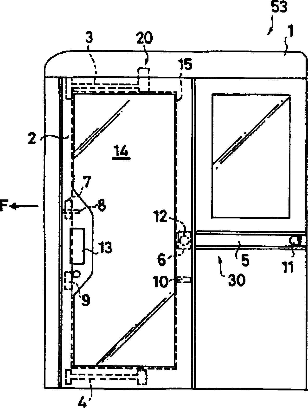
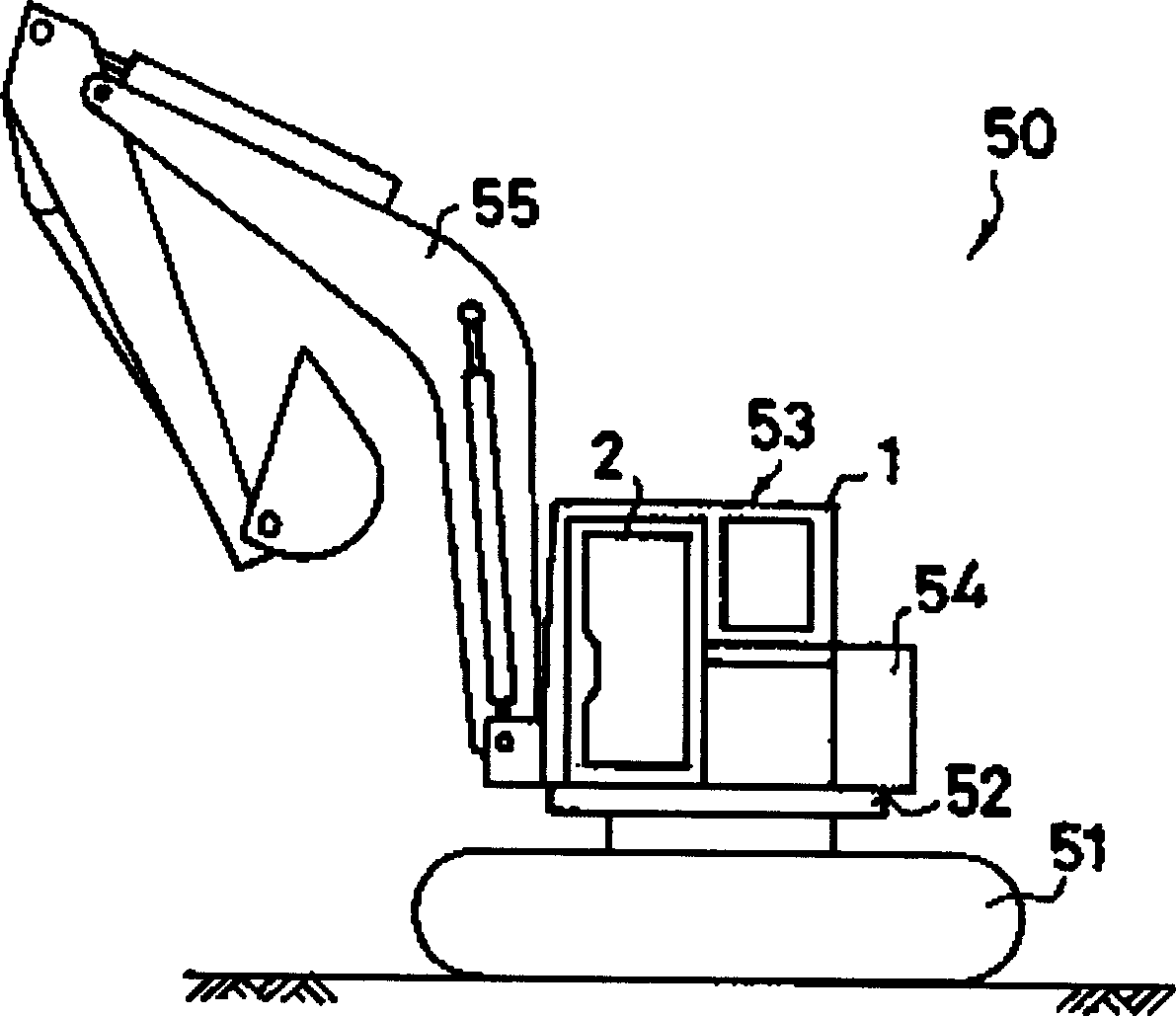
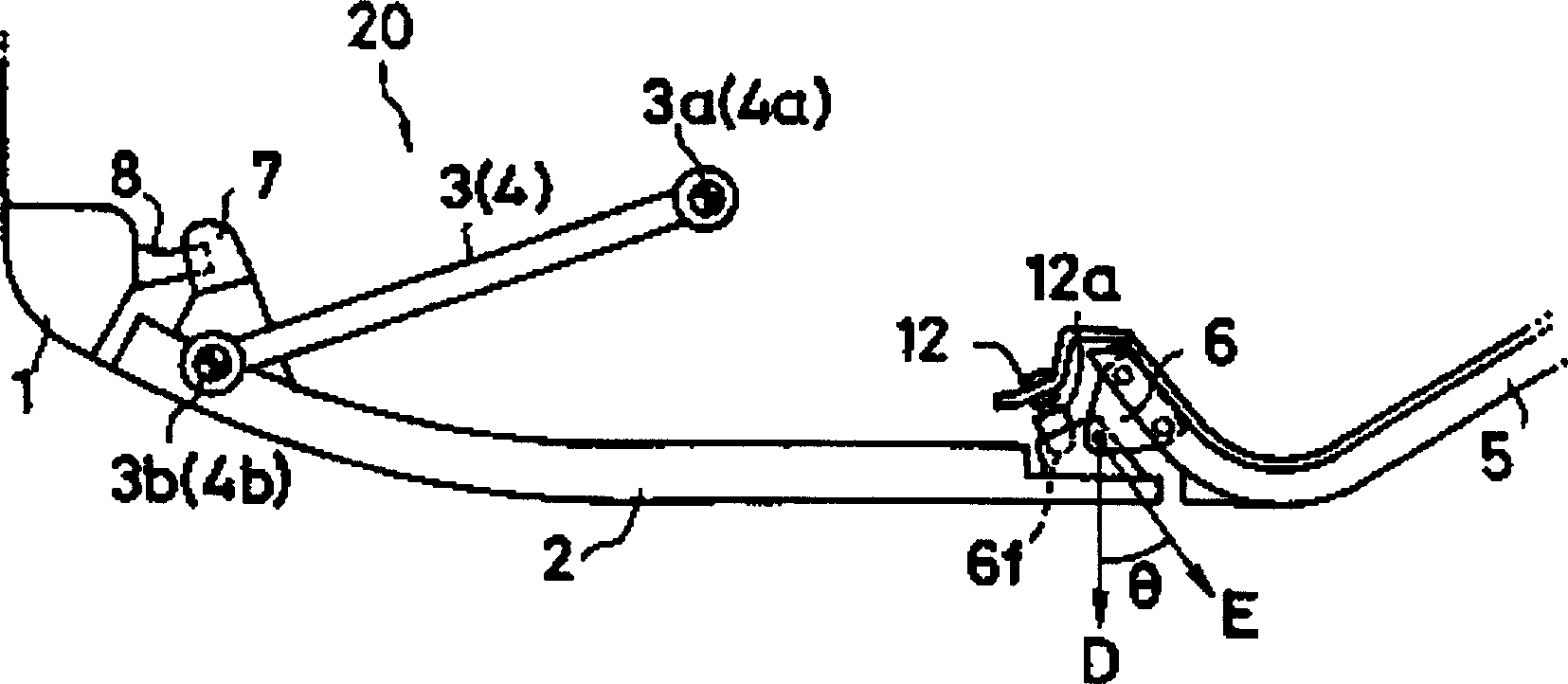
[0032] use figure 1 ~FIG. 8 demonstrates the first embodiment of the structure of the door 2 with which this cab 53 is assembled. In addition, in the following description, the closing direction of door 2 ( figure 1 The direction of the middle arrow F) is described as the front. door 2 as figure 1 As shown, the front part is assembled on the cab box body 1 by the link mechanism 20, and the rear part is assembled on the cab box body 1 by the sliding mechanism 30, so as to be formed on the cab box body 1 which can be opened and closed. And the entrance and exit 15 communicated with the cab space 1a are opened and closed. The link mechanism 20 is assembled to the upper link member 3 and the lower link at the upper and lower parts of the door 2 with one end pivotally connected to the cab box 1 in a swingable manner and the other end pivotally connected to the door 2 in a swingable manner. Composed of 4 parts. The sliding mechanism 30 is then composed of a sliding guide rai...

no. 2 example

[0050] In the first embodiment, the case where the front part of the door 2 is supported by the link mechanism 20 and the rear part is supported by the sliding mechanism 30 is described, but the front and rear parts may also be supported by the link mechanism or the sliding mechanism. Describe its composition. In addition, in the following description, the same components as those of the first embodiment are given the same reference numerals, and their descriptions are omitted.

[0051] First, use Figure 1 to Figure 13 A case where the front and rear parts of the door 2 are supported by the link mechanism 120 as the second embodiment will be described. In the second embodiment, the link mechanism 120 is composed of a front link member 103 and a rear link member 104 assembled side by side, one end (fixed end 103a, 104a) is connected to the upper part of the cab box body 1 in a swingable manner. The other end (movable end 103b, 104b) is pivotally connected to the front and re...

no. 3 example

[0057] use below Figure 14 ~ Figure 16 A case where only the front and rear parts of the door 2 are supported by the slide mechanisms 30, 230, 240 will be described as a third embodiment. In this third embodiment, the top of the front part of the door 2 is supported by an upper sliding mechanism 230, the bottom of the front part is supported by a lower sliding mechanism 240, and the substantially central part in the up-down direction of the rear part is supported by the same sliding mechanism 30 as in the first embodiment. support.

[0058] The upper sliding mechanism 230 is composed of an upper sliding guide rail 203 assembled on the cab box body 1 along the top edge of the entrance and exit formed on the cab box body 1 and an upper sliding member 303 that moves in a sliding manner along the upper sliding guide rail 203 , The lower sliding mechanism 240 is composed of a lower sliding guide rail 204 assembled on the cab box body 1 along the bottom edge of the entrance and a ...


PUM


Abstract

An operator cab 53 , which is mounted rotatable on the vehicle body 51 of a hydraulic mini-shovel 50 , comprises a cab box 1 , a door 2 , upper and lower link members 3 and 4 , a slide member 6 , a closed door lock 7 , an opened door lock 9 and a handle 13 . The cab box 1 has an internal cab room 1 a and an entrance 15 , which leads into the cab room 1 a. The door 2 closes and opens the entrance 15 when it is moved forward and rearward, respectively. The upper and lower link members 3 and 4 have fixed ends 3 a and 4 a, each of which is connected pivotally to the cab box 1 , and moving ends 3 b and 4 b, each of which is connected pivotally to the front end of the door 2 . The slide member 6 is connected pivotally to the rear end of the door 2 so as to swing freely and slides along a slide rail 5 , which is provided externally on the cab box 1 . The closed door lock 7 , which is provided at the front end of the door 2 , engages with a closed door striker 8 , which is provided on the cab box 1 , when the door 2 is closed. The opened door lock 9 , which is provided at the front end of the door 2 , engages with an opened door striker 10 , which is provided on the cab box 1 , when the door 2 is opened. The handle 13 is provided at the front end of the door 2 and interlocked with the closed door lock 7 and the opened door lock 9.

Description

technical field [0001] The present invention relates to a cab of a construction machine, and specifically relates to a cab of a construction machine having a door for opening and closing an entrance. Background technique [0002] A construction machine such as a hydraulic small excavator is configured to perform work by rotating a cab, a work machine, and the like disposed on a vehicle body. The door that is opened and closed to allow the operator to enter and exit the cab can be operated not only in the closed state but also in the open state. Figure 10 A large-scale construction machine 60 is shown, which has a turntable 62 rotatably provided on a vehicle body 61 , and a cab 63 is attached to the turntable 62 . In the case of such a large construction machine 60, the radius of rotation R' is relatively large, so even if the door 64 of the cab 63 is opened, the door 64 will not exceed the radius of rotation R', but the radius of rotation of the s...

Claims


Application Information

Patent Timeline
Patent Type & Authority Applications(China)
IPC IPC(8): B60J5/00E02F9/16E05D15/10E05D15/30
CPCE05D15/1005B60J5/0487E05Y2900/518E02F9/163
Inventor 中山真一新堰光寿
Owner TAKEUCHI SEISAKUSHOKK
Learn More