Method to correct for sensitivity variation of media sensors

A sensor and sensitivity technology, which is applied in the field of correcting the sensitivity change of media sensors, can solve problems such as difficult to produce reliable test tables

Inactive Publication Date: 2005-09-21
LEXMARK INT INC
View PDF0 Cites 2 Cited by
  • Summary
  • Abstract
  • Description
  • Claims
  • Application Information

AI Technical Summary

Problems solved by technology

If the spread becomes too large, e.g. if one sensor reads Rn = 7.0 for photo paper and another reads Rn = 11.0 for the same photo paper, then it is difficult to generate 1's Reliable Test Sheet

Method used


Image

  • Method to correct for sensitivity variation of media sensors
  • Method to correct for sensitivity variation of media sensors
  • Method to correct for sensitivity variation of media sensors

Examples


Embodiment Construction

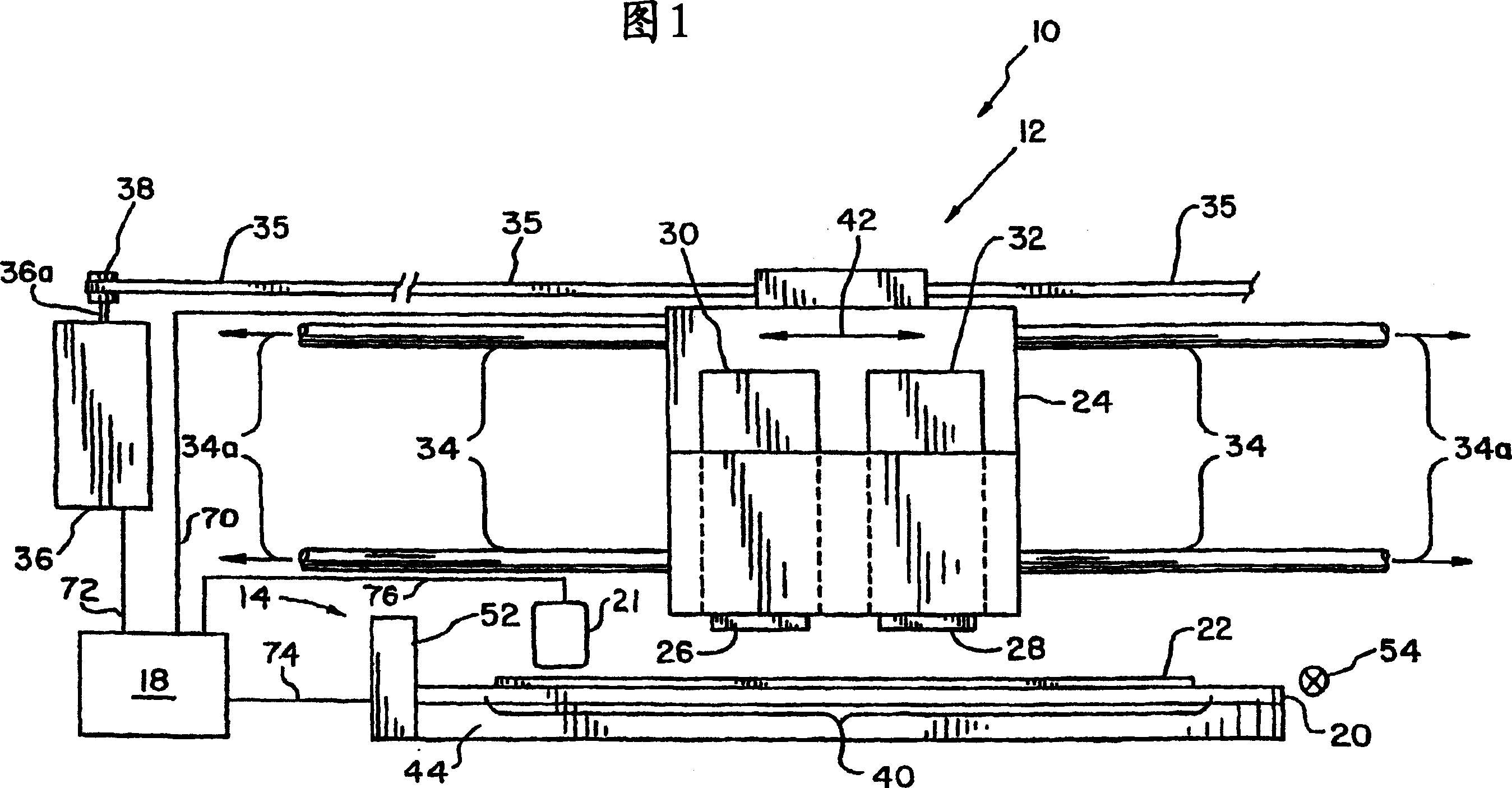
[0028] Referring now to the drawings, and particularly to FIG. 1, there is shown an inkjet printer 10 embodying the present invention. The inkjet printer 10 includes a printhead carrier system 12 , a feed roller unit 12 , a controller 18 , a mid-frame 20 and a media sensor 21 .

[0029] The printhead carrier system 12 includes a printhead carrier 24 for carrying a color printhead 26 and a black printhead 28 . A color ink reservoir 30 is provided in fluid communication with the color printhead 26 and a black ink reservoir 32 is in fluid communication with the black printhead 28 . The printhead carrier system 12 and printheads 26, 28 may be configured for unidirectional printing or bidirectional printing.

[0030] The printhead carrier 24 is guided by a pair of guide rods 34 . The axis 34a of the guide rod 34 defines the bi-directional scan path of the printhead carrier 24, so for convenience, the bi-directional scan path will be referred to as the bi-directional scan path 34a...


PUM


Abstract

A method of correcting for sensitivity variation of media sensors includes the steps of determining a first reflectance ratio RO of a first calibration media having a first glossiness G1 (S200); determining a second reflectance ratio R[HIGH] of a second calibration media having a second glossiness G2 (S202), the second glossiness G2 being greater than the first glossiness G1 and determining a corrected normalized reflectance ratio of an unknown media based on the first reflectance ratio of the first calibration media and the second reflectance ratio of the second calibration media (S206).

Description

technical field [0001] The present invention relates to media sensors, and more particularly, to a method of correcting for variations in sensitivity of a media sensor. Background technique [0002] A typical media sensor includes a single light source, such as a light emitting diode (LED), and a reflective detector, such as a phototransistor. Additionally, reflective detectors are usually located on the same side of the media as the light source. In operation, the LED emits light to the material surface of the media at a predetermined angle, and uses the amount of light reflected from the material surface received by the photodetector to check the surface characteristics of the media. The presence of the media is detected based on a predetermined amount of light reflected from the media to the reflective detector. [0003] Some sensors include a pair of reflective detectors, one arranged to detect reflected diffuse light and a second detector arranged to detect reflected ...

Claims


Application Information

Patent Timeline
Patent Type & Authority Applications(China)
IPC IPC(8): G01N21/27G01N21/57G01N21/86
CPCG01N2021/869G01N2021/8663G01N21/57G01N21/274G01N21/86
Inventor 玛赫森·切尔维翰迪莫西·L·安德森
Owner LEXMARK INT INC
Why Eureka
Try Eureka