


Quick Research
Generate reliable direction feasibility study reports for your R&D in just a few steps.

Technical Q&A
Discover and master advanced knowledge NOW. Basics, ideas, possibilities, all at once.

Find Solutions
As an expert in R&D theories, this can generate solutions to your technical problems instantly.

Evaluate Feasibility
Analyze your overall solution with one click, know your potential R&D risks in advance.

Monitor Landscape
Get weekly tech updates, stay abreast of the latest tech innovations and key insights.
Heating cooker
A technology for cookers and heating chambers, which is applied to electric heating fuel, lighting and heating equipment, household heating, etc. It can solve the problems of low detection accuracy of humidity sensors and unsatisfactory cooking results, and achieve good results and improve detection accuracy. Effect
- Summary
- Abstract
- Description
- Claims
- Application Information
AI Technical Summary
Problems solved by technology
Method used
Image

Examples
Embodiment approach 1
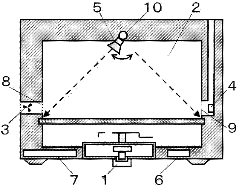
[0028] figure 1 It is a cross-sectional view showing the heating cooker according to Embodiment 1 of the present invention.
[0029] exist figure 1 Among them, the heating cooker of this embodiment has: a microwave generating unit 1; a heating chamber 2, which accommodates a load heated by microwaves; a fan 3, which sends air into the heating chamber 2; a humidity sensor 4, which measures the load in the heating chamber. The amount of steam in 2; the infrared sensor 5, which detects the temperature of the load in a non-contact manner; the load determination unit 6, which determines the load in the heating chamber 2 according to the temperature of the infrared sensor 5; and the control unit 7, which The speed of the fan 3 is controlled.
[0030] Usually, a magnetron is often used for the microwave generating unit 1 , but a semiconductor type or the like may be used.
[0031] In the microwave generating unit 1 , microwaves are generated by feeding power from an inverter circu...
Embodiment approach 2
[0081] Next, Embodiment 2 of the present invention will be described. The description of the same parts as those in Embodiment 1 will be omitted, and only the different points will be described.
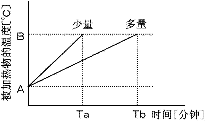
[0082] As described in Embodiment 1, the load amount determining means 6 detects the temperature of the load amount by the infrared sensor 5 to determine the load amount. Since the temperature rises quickly when the load is small, even if the control unit 7 stops the microwave generating unit 1 based on the detection result of the infrared sensor 5 or the humidity sensor 4, it is easy to heat to a temperature above the target temperature.
[0083] In order to prevent such a situation, in the present embodiment, when the load determined by the load determination unit 6 is determined to be “small”, the control unit 7 reduces the output of the microwave generation unit 1 . Thereby, it is possible to moderate the temperature rise rate of the load and improve the accuracy of bringing the...
Embodiment approach 3
[0086] Next, Embodiment 3 of the present invention will be described. The description of the same parts as those in Embodiment 1 will be omitted, and only the different points will be described.
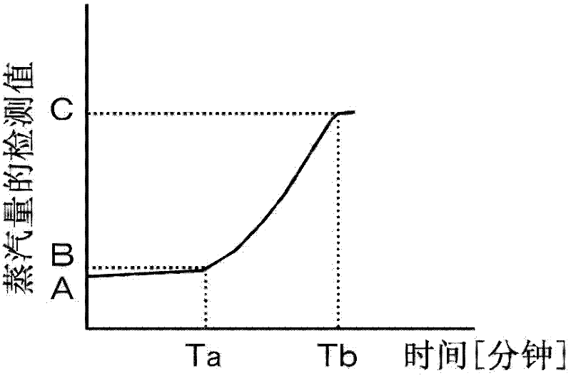
[0087] As described in Embodiment 1, when the load is small, the amount of steam generated is also small, and the humidity sensor 4 needs to capture the slight change, which is easily affected by noise and the like, resulting in a large error.
[0088] As one of the countermeasures, as described in Embodiment 1, there is proposed a method of increasing the detection accuracy by increasing the rotation speed of the fan 3 to send sufficient air to the humidity sensor 4 .
[0089] As another countermeasure, in the present embodiment, when the load determined by the load determination unit 6 is “small”, the control unit 7 intermittently repeats the rotation and stop of the fan 3 .
[0090] When the rotation of the fan 3 is stopped, there is no pressure from the outside, so the air in th...
PUM
 Abstract
Description
Claims
Application Information
 - R&D Engineer
- R&D Manager
- IP Professional
- Industry Leading Data Capabilities
- Powerful AI technology
- Patent DNA Extraction
Browse by: Latest US Patents, China's latest patents, Technical Efficacy Thesaurus, Application Domain, Technology Topic, Popular Technical Reports.
© 2024 PatSnap. All rights reserved.Legal|Privacy policy|Modern Slavery Act Transparency Statement|Sitemap|About US| Contact US: help@patsnap.com