
Cyclic preheater for single cavity permanent-magnet rotor pump and assembly method thereof

A permanent magnet rotor and pump circulation technology, applied in the direction of machine/engine, engine components, engine starting, etc., can solve problems such as unreasonable overall structure, achieve the effect of reducing the number of parts, reducing manufacturing costs, and simple molds

Inactive Publication Date: 2005-09-07
于佳衣
View PDF3 Cites 0 Cited by
  • Summary
  • Abstract
  • Description
  • Claims
  • Application Information

AI Technical Summary

Problems solved by technology

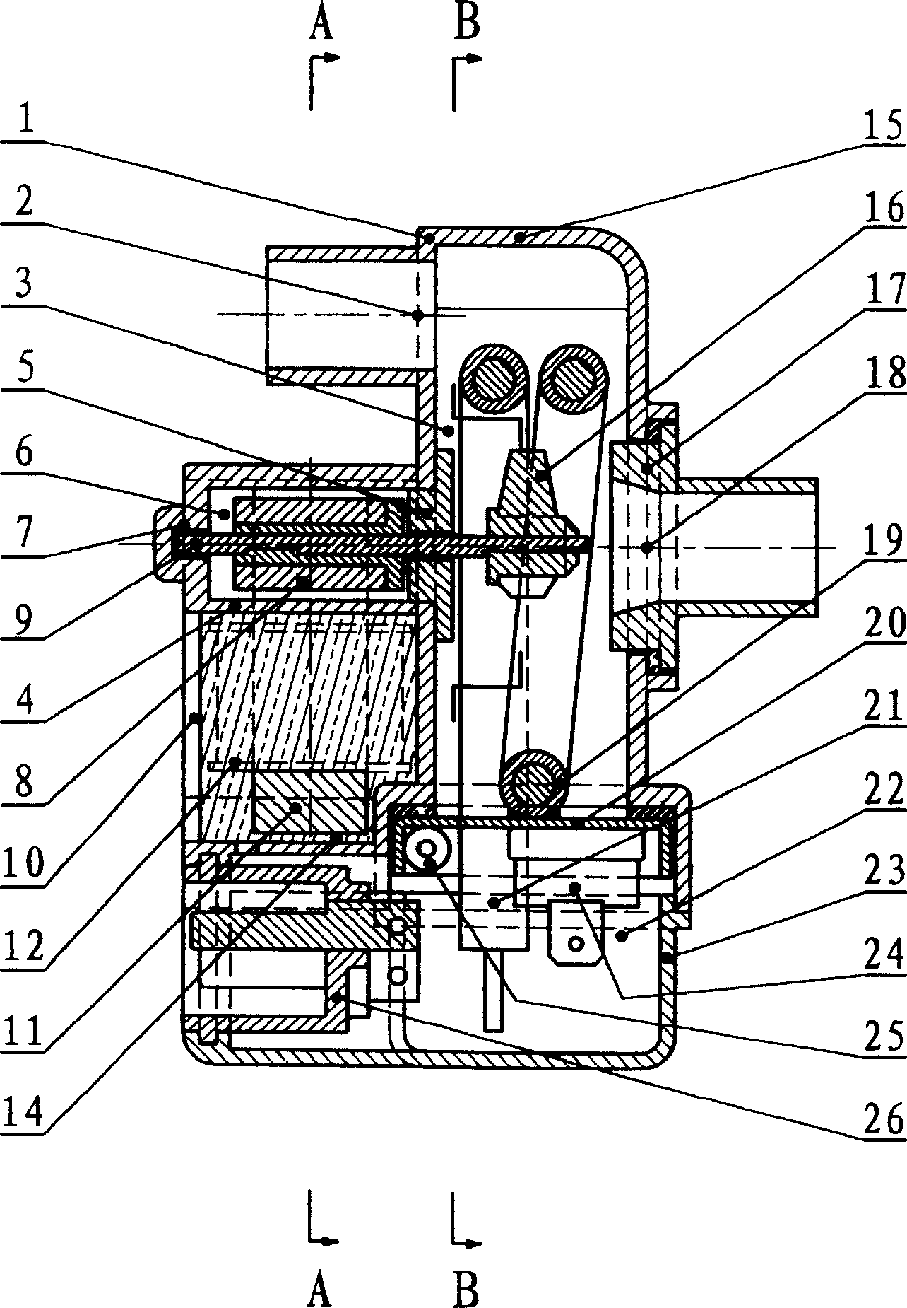
[0010] The purpose of the present invention is to propose a single-cavity permanent magnet rotor pump circulating preheater and its assembly method, which can more comprehensively solve the above-mentioned six defects of the prior art due to the unreasonable overall structure, and make the device simple in structure and easy to manufacture and assembly, improved sealing reliability, improved temperature measurement and temperature control accuracy, reliable overheat protection, good stator cooling and further miniaturization, reduced distance between inlet and outlet, easy to install

Method used


Image

  • Cyclic preheater for single cavity permanent-magnet rotor pump and assembly method thereof
  • Cyclic preheater for single cavity permanent-magnet rotor pump and assembly method thereof
  • Cyclic preheater for single cavity permanent-magnet rotor pump and assembly method thereof

Examples


Embodiment Construction

[0027] The specific implementation and examples of the present invention will be described below in conjunction with the accompanying drawings.

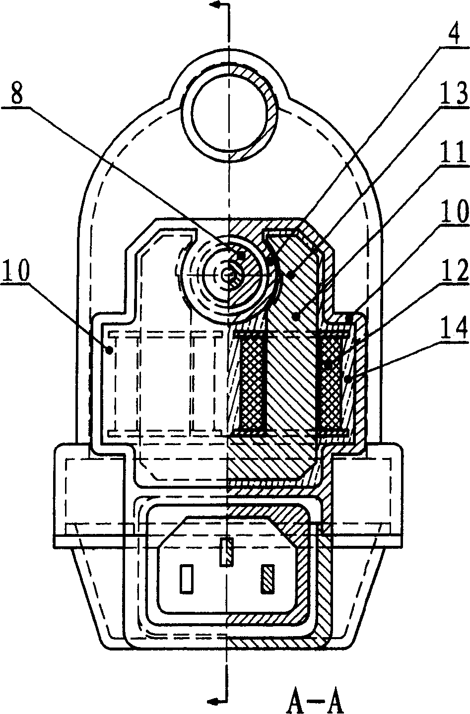
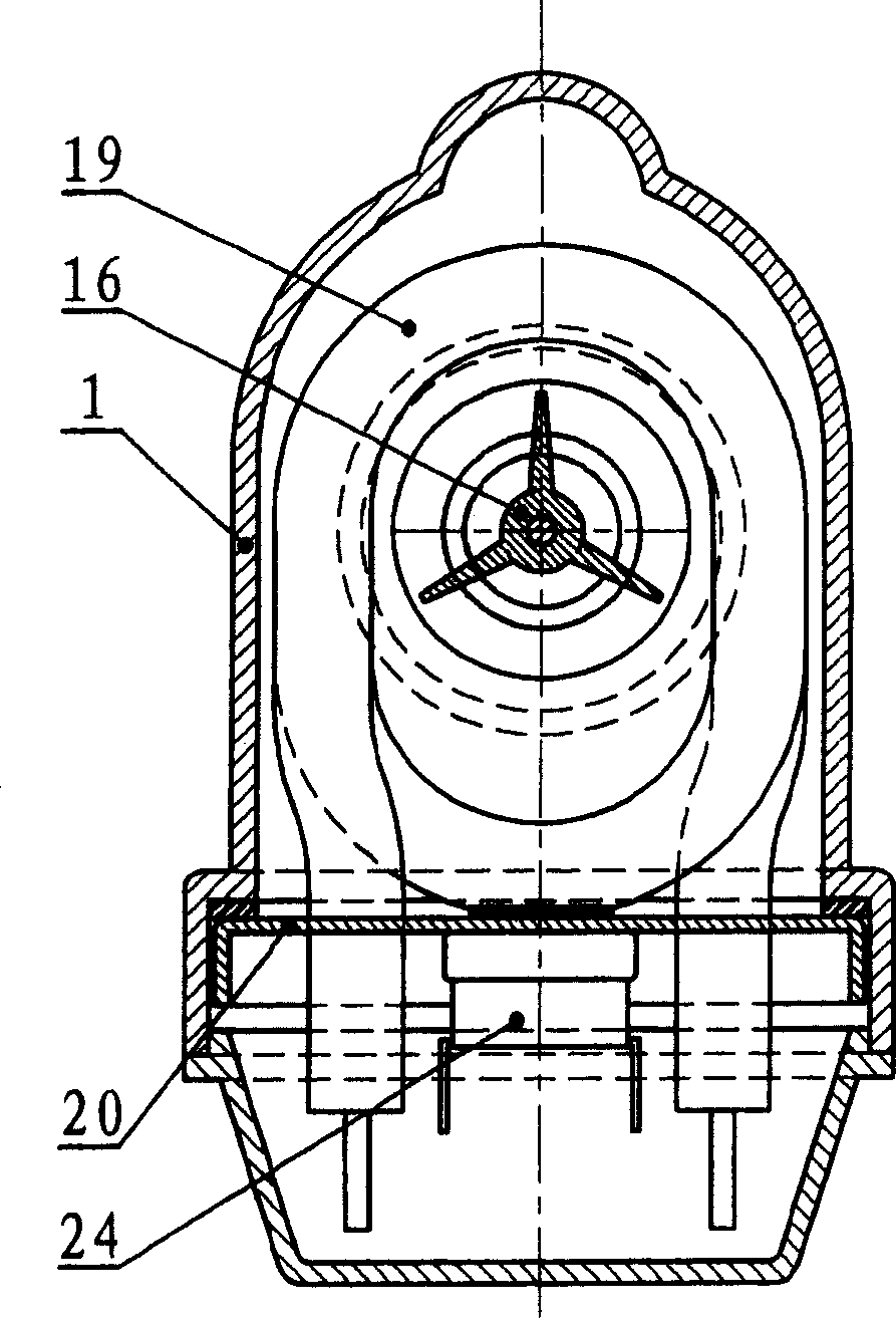
[0028] Depend on figure 1 , figure 2 , image 3 It can be seen that the main structure of the device of the present invention is a closed chamber, which communicates with the outside only through the inlet (18) and outlet (2) on it, and the chamber is divided into a smaller rotor chamber (6) and a larger heating chamber (3) Two parts, the two parts communicate through the rotor cavity, and the positional relationship between them is that the rotor cavity is on a side wall of the heating cavity (3), and the rotor cavity (6) protrudes outward from the rotor cavity Outside the heating chamber (3). Such a positional relationship shows that the rotor cavity opening is the interface between the rotor cavity (6) and the heating cavity (3). After the front bearing (5) is installed on the rotor cavity opening, the front bearing (5) connec...


PUM


Abstract

The invention relates to a single cavity permanent-magnet rotor pump cycle preheater and the installation method that belongs to the preheating field for the engine of automobile. The feature is that: the cavity is made up of cavity main body, front cover and electric heating pipe fixed disk; the cavity main body is manufactured by the method of plastic injecting modeling and rotor cavity, outlet, front cover mouth, electric heating pipe mouth, stator groove are set on it; the permanent-magnet rotator, front bearing and impeller are installed into the heating cavity from the front cove mouth. The spirality part of the electric heating pipe is installed in the heating cavity from heating pipe mouth. The stator is fixed in stator groove. The temperature sensors are installed on the out side of the electric heating pipe fixed disk. The junction box is installed under the fixed disk and the stator groove. The electric heating pipe component should be installed first.

Description

technical field [0001] The invention relates to a single-cavity permanent magnet rotor pump circulation preheater and its assembly method, which belongs to the field of motor vehicle engine electric preheaters, and can also be applied to preheating, heating, temperature control, etc. of other engines and other machinery and equipment field. Background technique [0002] In a low temperature environment, motor vehicle engines will have difficulty starting due to fuel condensation, oil viscosity and other reasons. The most ideal way to solve this problem is to heat the engine in advance, this process is generally called warm-up. Through preheating, the cold start becomes a hot start, which not only starts smoothly, but also greatly reduces engine wear, and can also greatly reduce the emission of polluting gases in the engine exhaust and reduce fuel consumption. [0003] In order to achieve preheating, a preheater is usually installed on the engine. Compared with other prehe...

Claims


Application Information

Patent Timeline
Patent Type & Authority Applications(China)
IPC IPC(8): F02N19/10
Inventor 于昊昱衣美凤
Owner 于佳衣
Learn More