
Structure of water tank of having heat sink in liquid cooling type

A cooling device and water tank technology, applied in the direction of instruments, electrical digital data processing, digital data processing components, etc., can solve the problems of loss of grain structure precision, high cost, and reduced structural strength

Inactive Publication Date: 2005-08-31
FORWARD ELECTRONICS CO LTD
View PDF0 Cites 0 Cited by
  • Summary
  • Abstract
  • Description
  • Claims
  • Application Information

AI Technical Summary

Problems solved by technology

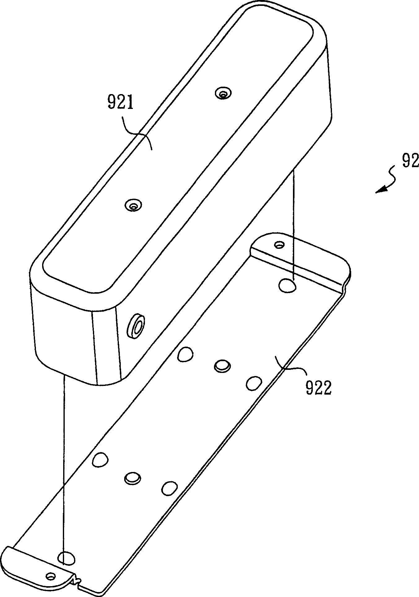
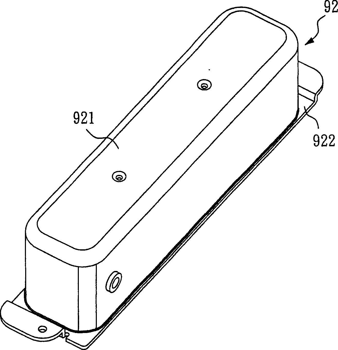
However, the cost of the general deep-drawing processing method is relatively high, and the upper cover 921 has a relatively deep depth, generally about 50mm, so it must be completed by multiple deep-drawing processes, known to be more than three times, so The surface of the upper cover 921 is wrinkled, and the upper cover 921 forms the same grain direction after multiple deep drawing processes, and then loses the fineness of the grain structure, and it is easy to cause the internal liquid molecules to escape and dry up for a long time. And multiple deep drawing processes will destroy its internal grain structure and reduce its structural strength, which is not very ideal

Method used


Image

  • Structure of water tank of having heat sink in liquid cooling type
  • Structure of water tank of having heat sink in liquid cooling type
  • Structure of water tank of having heat sink in liquid cooling type

Examples


Embodiment Construction

[0018] In order to better understand the technical content of the present invention, a preferred specific embodiment is given as follows.

[0019] Please refer to FIG. 4 , which is an exploded perspective view of the present invention, which shows a water tank structure of a liquid-cooled heat sink of the present invention, which mainly includes a hollow tube body 1 and two side plates 2 , 3 .

[0020] Please also refer to Figure 4, Figure 5 It is a schematic diagram of the manufacturing method of the hollow tube body of the present invention, and Figure 6 It is a three-dimensional combination diagram of the present invention, wherein, the above-mentioned hollow pipe body 1 is a square pipe body and is formed by extrusion (such as Figure 5 shown), and the hollow pipe body 1 is made of copper metal, of course, other metal materials, such as aluminum, can also be used. In addition, the aforementioned hollow tube body 1 includes an internal chamber 11, and an opening 12, 13 ...


PUM


Abstract

The present invention relates to a water tank structure of liquid-cooled heat radiation equipment. It is characterized by that on two ends of a hollow pipe body an opening is formed respectively, and the every opening is sealed with a side plate so as to form a water tank structure. The described hollow pipe body is made up by adopting press forming process.

Description

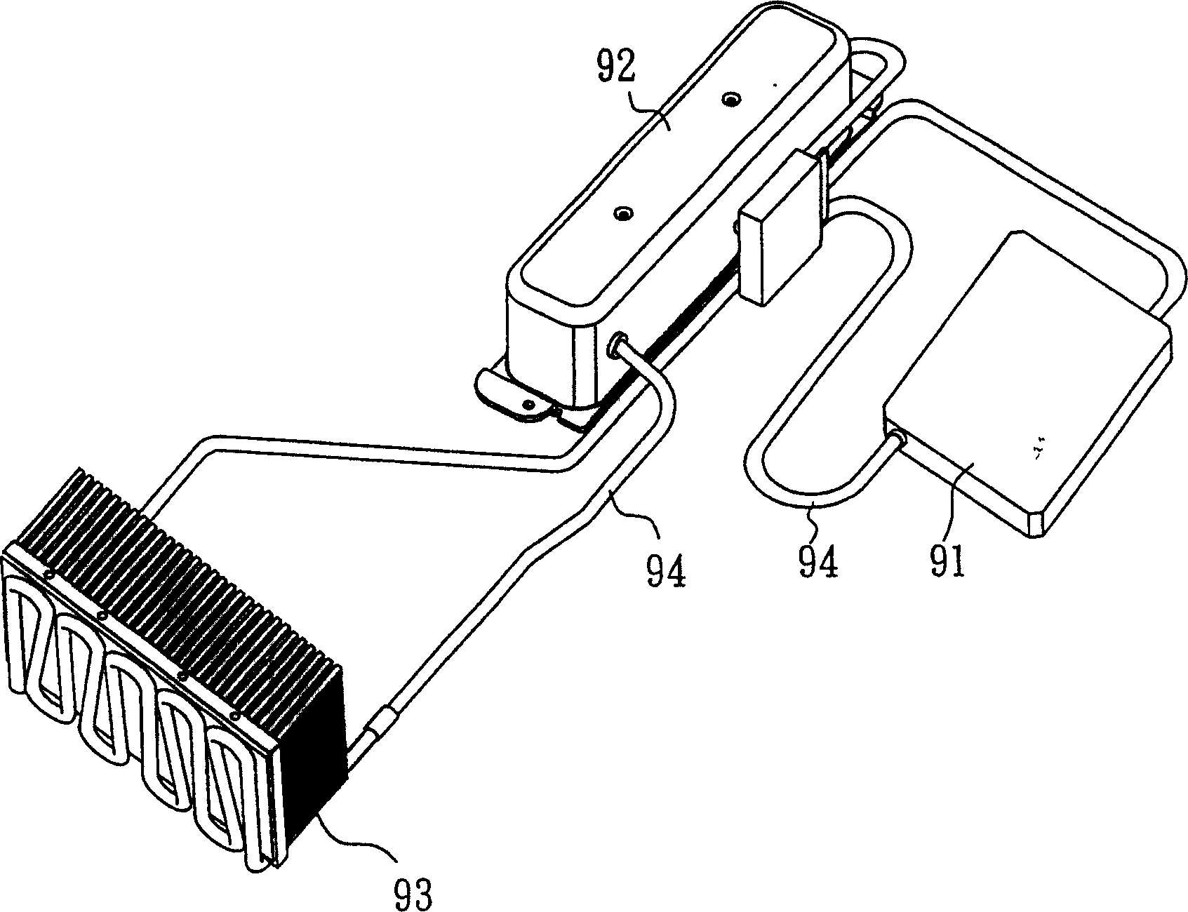
technical field [0001] The invention relates to a water tank structure of a liquid-cooled heat dissipation device, in particular to a water tank structure suitable for a liquid-cooled heat dissipation device of a computer device. Background technique [0002] In a general computer device, the main heat-generating electronic component inside it is its central processing unit (CPU). use efficiency. [0003] see figure 1 It is a three-dimensional view of an existing liquid-cooled heat sink, which mainly includes a heat collecting unit 91, a water tank 92, and a heat dissipation unit 93, wherein the heat collecting unit 91 is used to collect heat-generating electrons such as the above-mentioned central processing unit (CPU). The heat generated by the components is brought to the heat dissipation unit 93 through the heat dissipation liquid (such as pure water) in the heat pipe 94 for dissipating, and the water tank 92 is used to store the heat dissipation liquid used by the ove...

Claims


Application Information

Patent Timeline
IPC IPC(8): G06F1/20
Inventor 黄荣峰黄志坚
Owner FORWARD ELECTRONICS CO LTD
Learn More