Method for removing contaminants from gases
A carbon dioxide and catalyst technology, applied in the field of purifying carbon dioxide, can solve problems such as being unsuitable for removal
- Summary
- Abstract
- Description
- Claims
- Application Information
AI Technical Summary
Problems solved by technology
Method used
Image
Examples
Embodiment 1
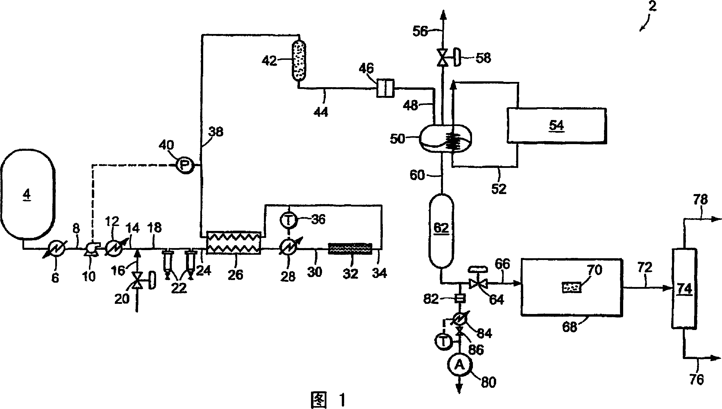
[0093] Carbon dioxide was purified in a system similar to system 2 shown in FIG. 1 . CO2 is withdrawn from the vapor field of a CO2 cylinder containing SFE grade CO2. The cylinder contained saturated liquid at room temperature and a pressure of about 820 psia (about 5654 kPa). The vapor is then passed through a coalescing filter operating at cylinder pressure. The stream is reduced in pressure and passed through a 0.003 micron electronic grade particulate filter to remove solids. Heat is applied upstream of the pressure reduction device to ensure that the carbon dioxide entering the downstream particle analyzer is near room temperature. Figure 5 The number of particles is shown as a function of the pressure to which the stream is depressurized. At the highest pressure, the drop in pressure is less and the number of particles is lower. This is consistent with the use of high efficiency coalescing filters. However, when the pressure is further reduced, many submicron-sized...
Embodiment 2
[0095]EIG carbon dioxide liquid at a pressure of 300 psig (approximately 2068 kPa) is withdrawn from the storage tank, evaporated, and passed through a thermal catalytic reactor. The catalytic reactor included three PRO*VOC 10 catalysts, all products of Sud-Chemie Prototech, Inc. (Needham, MA). PRO*VOC 10 catalysts are platinum-based metal catalysts supported on porous ceramics. The reactor was operated at different temperatures ranging from ambient (about 21.1°C) to 315.6°C. In all tests, the space velocity was 44,000 scfh / ft 3 (44,000 standard cubic meters per hour per cubic meter of catalyst volume). Oxygen was added to the carbon dioxide upstream of the reactor such that the mixture contained 600 ppm oxygen by volume.
[0096] Figure 6 The particle size distribution is shown as a function of the reactor temperature, where the particles are measured downstream of the reactor at room temperature and pressure about the same as the reactor. Particle counts were measured ...
Embodiment 3
[0101] EIG carbon dioxide was passed through a catalytic reactor containing three PRO*VOC 10 catalysts (platinum-based metal / porous ceramic) as described in Example 2, again without condensation prior to the reactor. The reactor temperature was 600°F (315.5°C) and excess oxygen (approximately 600 ppm by volume) was added to the stream. Under the conditions described above, particle counts at reactor pressure and room temperature showed essentially complete disappearance of the particles.
[0102] Figure 8 Parallel analysis of streams at two space velocities in a low-pressure particle analyzer operating near room temperature and ambient pressure is shown. When measured at normal temperature and pressure, the number of particles in the steam supplied to the catalytic system exceeds 10 per cubic foot 7 (about 353 million particles per cubic meter). When at NTP, at space velocities of 140,000 and 70,000 scfh / ft respectively 3 Downstream of the reactor, it drops to about 600 a...
PUM
| Property | Measurement | Unit |
|---|---|---|
| diameter | aaaaa | aaaaa |
| critical temperature | aaaaa | aaaaa |
| size | aaaaa | aaaaa |
Abstract
Description
Claims
Application Information
 - R&D
- Intellectual Property
- Life Sciences
- Materials
- Tech Scout
- Unparalleled Data Quality
- Higher Quality Content
- 60% Fewer Hallucinations
Browse by: Latest US Patents, China's latest patents, Technical Efficacy Thesaurus, Application Domain, Technology Topic, Popular Technical Reports.
© 2025 PatSnap. All rights reserved.Legal|Privacy policy|Modern Slavery Act Transparency Statement|Sitemap|About US| Contact US: help@patsnap.com


