
Planar light waveguide measuring apparatus for micro-displacement

A planar optical waveguide and measuring device technology, which is applied in the directions of measuring devices, using optical devices, and using optical devices to transmit sensing components, can solve the problems of limited use, high cost, complex structure, etc. Simple process, easy to achieve effect

Inactive Publication Date: 2005-07-27
SHANGHAI JIAO TONG UNIV
View PDF0 Cites 15 Cited by
  • Summary
  • Abstract
  • Description
  • Claims
  • Application Information

AI Technical Summary

Problems solved by technology

This dual-arm modulated laser interferometer needs necessary equipment such as a function generator, a lock-in amplifier, and a low-noise amplifier, which makes the entire structure more complicated and costly, limiting its widespread use.

Method used


Image

  • Planar light waveguide measuring apparatus for micro-displacement
  • Planar light waveguide measuring apparatus for micro-displacement
  • Planar light waveguide measuring apparatus for micro-displacement

Examples


Embodiment Construction

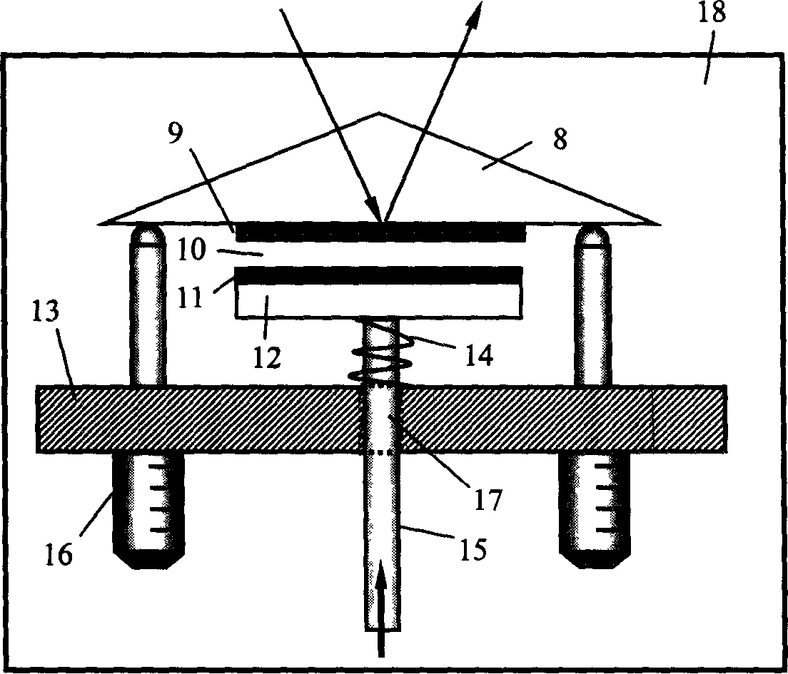
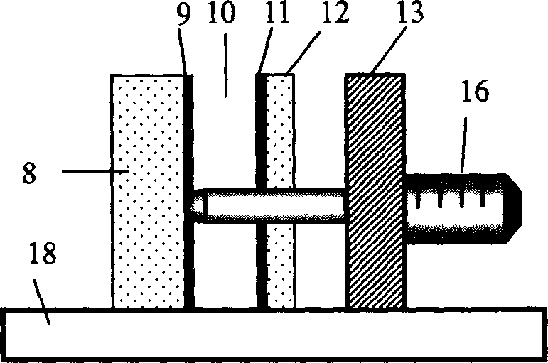
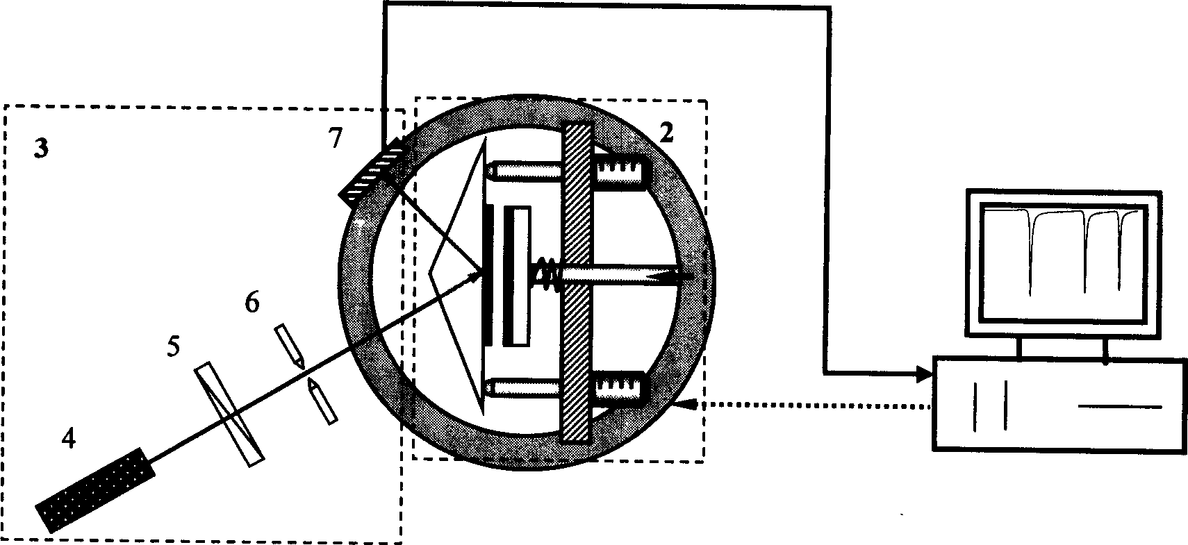
[0014] Such as Figure 1 to Figure 3 As shown, the device of the present invention is composed of an optical rotating platform 1, an optical waveguide micro-displacement sensor 2, and a photodetecting part 3. The optical waveguide micro-displacement sensor 2 is fixed on the optical rotating platform 1, and the optical rotating platform 1 supports the entire optical waveguide micro-displacement Sensor 2, photoelectric detection part 3 includes: laser 4, polarizer 5, optical aperture 6, photodetector 7, laser 4, polarizer 5, optical aperture 6 are fixed outside the optical rotating platform 1, and they maintain the same height. The optical axis points to the center of the optical waveguide micro-displacement sensor 2. The photodetector 7 and the laser 4 are symmetrical about the central axis of the optical waveguide micro-displacement sensor 2. At the same time, the photodetector 7 is fixed on the optical rotating platform 1, and the optical rotating platform 1 When the position of t...


PUM


Abstract

An optical waveguide microdisplacement transducer setting on optical rotary table comprises photoelectric unit including laser, polarimeter, optical eyelets and photoelectric detector. It is featured as fixing optical eyelets at external of optical rotary table with the same height in coaxis to point optical axis to center of the transducer, setting photoelectric detector and laser in symmetry to center line of the transducer and fixing photoelectric detector on optical rotary table for measuring microdisplacement of dam, building and earth crust.

Description

Technical field [0001] The invention relates to a micro-displacement measuring device, in particular to a micro-displacement optical waveguide measuring device. It belongs to the field of precision measuring instruments. Background technique [0002] Measuring micro-displacement has a wide range of applications in long-term monitoring of buildings, bridges and earthquake detection. Laser interferometer is a traditional instrument for micro-displacement measurement. The laser interferometer usually consists of two arms, one is the reference arm and the other is the detection arm. After the laser light emitted from the semiconductor laser passes through the beam splitter, the light is divided into two paths. After one light passes through the beam splitter, it continues to travel along the original propagation direction and enters the light path A, and the other light is reflected and enters the light path B. Mirrors are installed at the ends of optical path A and optical path B. T...

Claims


Application Information

Patent Timeline
IPC IPC(8): G01B11/16G01D5/26
Inventor 陈凡曹庄琪沈启舜邓晓旭冯耀军
Owner SHANGHAI JIAO TONG UNIV
Learn More