Monitor system
A monitoring system and central technology, applied in the field of monitoring systems, can solve problems such as inconvenient identification
- Summary
- Abstract
- Description
- Claims
- Application Information
AI Technical Summary
Problems solved by technology
Method used
Image


Examples
no. 1 example
[0032] figure 1 A schematic configuration diagram of a monitoring system according to the present invention is shown. The monitoring system according to the present invention is a security system for preventing crime in a house which has a function of intimidating and notifying when a burglary is detected and a function of notifying a predetermined target when an emergency occurs in a house.
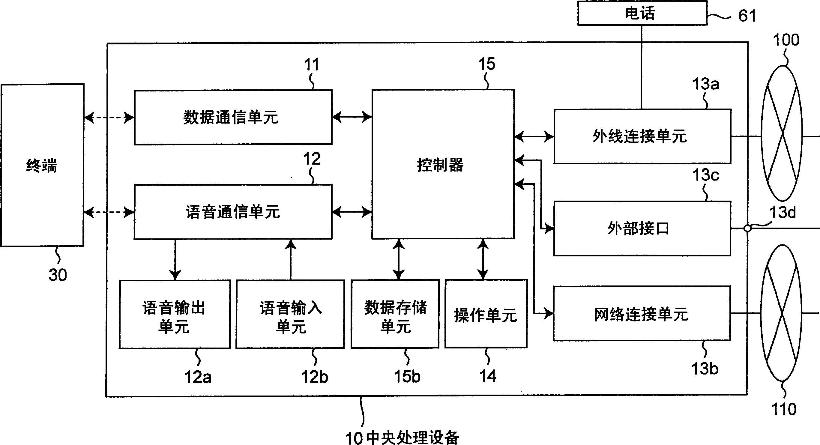
[0033] Such as figure 1 As shown, the monitoring system includes a central processing device 10 and a plurality of terminals 31 to 35 . The central processing device 10 and the terminals 31 to 35 are connected to each other by wireless communication means. As communication means, a specific low-power wireless network (ECHONET) can be used.
[0034] The central processing device 10 is connected to a public telephone network 100 to which communication devices such as landline phones 71 and 73 and a mobile phone 72 are connected, and to the Internet 110 to which a data server 75 is conne...
no. 2 example
[0078] Figure 5 A suitable diagram showing another configuration of a central processing device in a monitoring system. The second embodiment differs from the first embodiment in the way of communication between the central processing device and the terminal. More specifically, in the first embodiment (see figure 2 ), the data and voice communication units 11 and 12 are installed independently. In this embodiment, the communication unit is integrated through multiplexing and demultiplexing of data and audio signals.
[0079] exist Figure 5 Among them, the central processing device 10a according to the present invention includes a data processing unit 16 for processing data, a voice processing unit 17 for modulating and demodulating audio signals, and a mixing / decomposing communication unit for multiplexing data and voice signals 18.
[0080] When data and audio signals are transmitted from the central processing device 10a, the mixing / decomposing communication unit 18 ...
no. 3 example
[0088] In this embodiment, the system configuration can make the terminal check whether the external telephone or the central processing device safely accepts the notification of the occurrence of an emergency or the operation specified by the user from the terminal.
[0089] Figure 7 A block diagram showing the configuration of a terminal equipped with an emergency call key. Such as Figure 7 As shown, the terminal 34 a according to this embodiment includes a data communication unit 41 , a controller 46 , an emergency call key 47 , a display unit 51 , and a notification unit 52 . The emergency call key 47 is arranged as a key switch. The user presses the keyswitch to notify that an emergency has occurred.
[0090] When the controller 46 received an abnormal state signal (a signal indicating that the user was in an abnormal situation) from the emergency call key 47, the controller 46 utilized the data communication unit 41 to wirelessly send an abnormal signal comprising a...
PUM
 Abstract
Description
Claims
Application Information
 - Generate Ideas
- Intellectual Property
- Life Sciences
- Materials
- Tech Scout
- Unparalleled Data Quality
- Higher Quality Content
- 60% Fewer Hallucinations
Browse by: Latest US Patents, China's latest patents, Technical Efficacy Thesaurus, Application Domain, Technology Topic, Popular Technical Reports.
© 2025 PatSnap. All rights reserved.Legal|Privacy policy|Modern Slavery Act Transparency Statement|Sitemap|About US| Contact US: help@patsnap.com