
Display device and used display panel, pixel circuit and compensating mechanism

A pixel circuit and display panel technology, applied in measuring devices, static indicators, instruments, etc., can solve problems such as poor output current stability and deteriorating brightness

Active Publication Date: 2005-06-29
AU OPTRONICS CORP
View PDF0 Cites 20 Cited by
  • Summary
  • Abstract
  • Description
  • Claims
  • Application Information

AI Technical Summary

Problems solved by technology

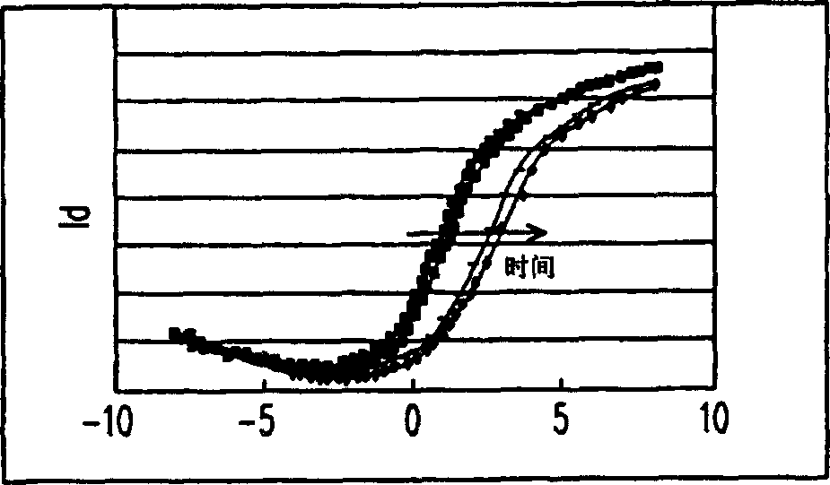
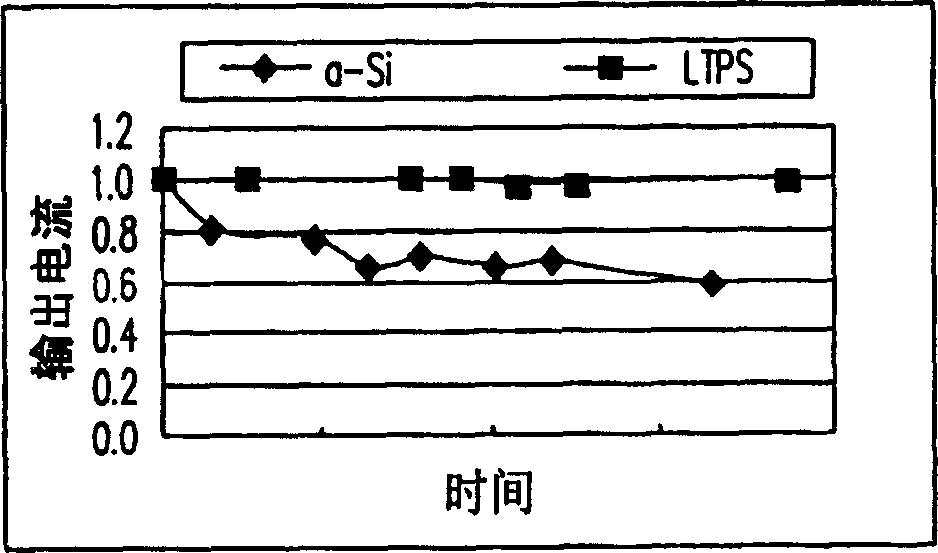
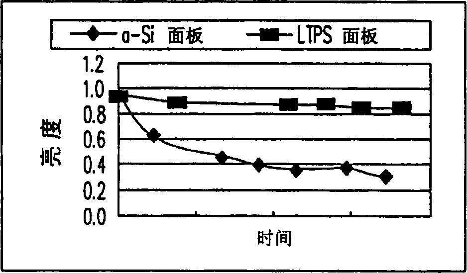
In contrast to amorphous silicon TFT, due to the poor stability of its output current, the brightness of the AMOLED display using amorphous silicon TFT will go from bad to worse after working for a period of time.

Method used


Image

  • Display device and used display panel, pixel circuit and compensating mechanism
  • Display device and used display panel, pixel circuit and compensating mechanism
  • Display device and used display panel, pixel circuit and compensating mechanism

Examples


Embodiment Construction

[0053] Figure 2A A block diagram of an internal circuit of a display device according to a preferred embodiment of the present invention is shown. Please refer to Figure 2A , in the display device provided by the present invention, there is a display panel 310, which is respectively coupled to the gate driving circuit 321 and the source driving circuit 323 by means of scanning lines G1~Gm-1 and data lines D1~Dn. In addition, in the present invention, a timing control circuit 330 is also included for controlling the gate driving circuit 321 and the source driving circuit 323 to drive the display panel 310 to output images. In addition, in the embodiment of the present invention, redundant scan lines are further configured. Due to the limitations of the manufacturing process, the present invention arranges the redundant scanning lines on the outermost sides of the scanning lines G1~Gm-1, that is, Figure 2A Depicted are two solid lines denoting G0 and Gm. It is worth menti...


PUM


Abstract

It is display device with time sequence control circuit, programmable voltage generator, grating and source drive circuit and display panel. Wherein the redundant picture element unit and display picture element unit is formed with non-silicon thin film transistor and organic light diode. This invention can compare the working current of each display picture element unit and relative redundant picture element unit. Then the time sequence control circuit can compensate the current of the display unit after working a while according to the comparing results.

Description

technical field [0001] The invention relates to a detection technology of a display device, in particular to a detection technology of a display device using an organic light emitting diode as a pixel component. Background technique [0002] Due to the rapid progress of the multimedia society, the technologies of semiconductor components and display devices have also made rapid progress. As far as the display is concerned, since the thin film transistor-active matrix organic light emitting diode (Thin Film Transistor-Active Matrix Organic Light Emitting Diode, hereinafter referred to as TFT-AMOLED) display has no viewing angle limitation, low manufacturing cost, high response speed (about a hundred times that of liquid crystal Above), power saving, can be used for DC drive of portable machines, wide operating temperature range, light weight and can be miniaturized and thinned with hardware equipment, etc., so it meets the characteristic requirements of displays in the multim...

Claims


Application Information

Patent Timeline
Patent Type & Authority Applications(China)
IPC IPC(8): G01R31/00G09G3/20G09G3/3233G09G3/3266G09G3/3275
Inventor 李易书
Owner AU OPTRONICS CORP
Learn More