
Light source output control method and system, and laser projection device

An output control and light source technology, applied in optics, instruments, projection devices, etc., can solve the problems of reduced monochromatic light brightness and high difficulty in assembly process, and achieve the effect of eliminating color mixing and ensuring color brightness and timing.

Active Publication Date: 2016-01-06
QINGDAO HISENSE LASER DISPLAY CO LTD
View PDF9 Cites 17 Cited by
  • Summary
  • Abstract
  • Description
  • Claims
  • Application Information

AI Technical Summary

Problems solved by technology

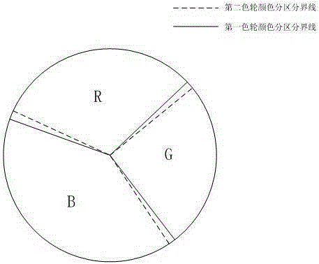
[0005] One way to remove color mixing in the prior art is to adopt a coaxial structure for the two-color wheel, that is, a coaxial connection. In this structural mode, the boundary line of the same color partition in the phosphor wheel and the color filter wheel needs to be accurately Correspondence, that is, the projections along the axial direction of the boundary line of the same color partition on the two wheels coincide, but due to the high difficulty of the assembly process, the offset error caused by processing and installation will always exist due to the fixation of the two color wheels and the rotating shaft. The resulting color mixing phenomenon can only ensure the purity and timing of the color output by eliminating the color mixing period, resulting in a reduction in the brightness of monochromatic light

Method used


Image

  • Light source output control method and system, and laser projection device
  • Light source output control method and system, and laser projection device
  • Light source output control method and system, and laser projection device

Examples


Embodiment 1

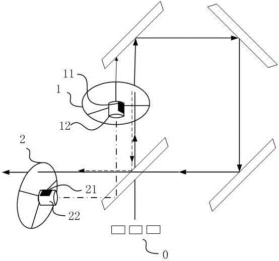
[0041] The present invention aims to provide a light source output control method, which is applied to a light source with a non-coaxial design of two-color wheels. The light source as figure 2 As shown, including laser 0, first color wheel 1 and second color wheel 2. Wherein, the laser 0 emits laser light, irradiates the first color wheel 1 to generate fluorescence, and the laser light and the fluorescence emit through the corresponding color zones on the second color wheel 2 respectively. The first color wheel 1 and the second color wheel 2 have the same color division, so that laser light and fluorescent light can pass through the two color wheels corresponding to the same color division at the same time.

[0042] An example of the non-coaxial position and structure relationship of the two-color wheel can be as follows figure 2 As shown, the first color wheel 1 and the second color wheel 2 are respectively connected with driving motor shafts 12 and 22 to drive the wheel...

Embodiment 2

[0056] Embodiment 2 of the present invention is an improvement and refinement on the basis of Embodiment 1.

[0057] Wherein, for step S1: according to the acquired first group of sensing signals of the first synchronization mark and the second synchronization mark, synchronizing the first color wheel and the second color wheel specifically includes: Figure 6 Shown:

[0058] Step S11: Within one rotation period, respectively acquire sensing signals corresponding to the first synchronization mark and the second synchronization mark, which are recorded as the first group of sensing pulse signals.

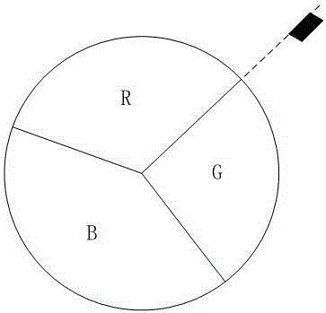
[0059] In this embodiment of the method, the synchronous mark can be a black film or black tape or a carbonized mark. Black has a light-absorbing effect, so when the signal sent by the sensor encounters the above-mentioned black mark on the surface of the rotating shaft during the rotation of the driving motor shaft is absorbed, and the non-marked part on the side of the motor shaft...

Embodiment 3

[0082] Based on the above light source output control method, the embodiment of the present invention also proposes a light source output control system, such as Figure 13 As shown, a first color wheel 21 is included, and the first color wheel 21 includes a first synchronization mark (not shown in the figure); a second color wheel 22, and the second color wheel 22 includes a second synchronization mark (not shown in the figure). ), where the first synchronization mark corresponds to the position of the second synchronization mark on the corresponding color wheel, the system also includes a first sensor 23 , a second sensor 24 , a third sensor 25 and a control unit 26 .

[0083] Wherein, the first sensor 23 is used to detect and obtain the sensing signal of the first synchronization mark of the first color wheel, which is an infrared sensor or a light sensor; the second sensor 24 is used to detect and obtain the second synchronization of the second color wheel The sensing sign...


PUM


Abstract

The invention discloses a light source output control method, comprising: non-coaxially arranging a first color wheel and a second color wheel which are respectively provided with a first mark and a second mark, and synchronizing the first color wheel and the second color wheel according to an obtained first set of induction signals of a first synchronous mark and a second synchronous mark; and obtaining second induction signals from the output light path of the second color wheel, and synchronizing the first color wheel and the second color wheel again according to the second induction signals, wherein the second induction signals are voltage waveform signals corresponding to different colors, and sequentially output three primary colors when passing the second color wheel. Accordingly, the method can synchronize the two color wheels accurately, eliminate color mixing in outputting the second color wheel, improve the homogeneous light purity and brightness of the three primary colors, and provide a high quality lighting light source. The invention also provides a control system corresponding to the light source output control method, and a laser projection device using the control system and method.

Description

technical field [0001] The invention relates to the technical field of laser light sources, in particular to a method and system for synchronous control of a two-color wheel of a light source, and a laser projection device. Background technique [0002] At present, the laser light source used in the industry is composed of laser light and fluorescence generated by the stimulation of phosphor powder. Usually, the blue laser is used as the excitation light source, and it is also used as blue light, one of the three primary colors of red, green and blue. A fluorescent wheel is a wavelength conversion device used to generate the other two primary colors of light in addition to blue light. In an implementation of the prior art, when the blue laser hits the fluorescent wheel, the green phosphor and the yellow phosphor are excited to generate green light and yellow light respectively, which are filtered by the green filter and the red filter of the color wheel. Green and red light...

Claims


Application Information

Patent Timeline
Patent Type & Authority Applications(China)
IPC IPC(8): G03B21/20
CPCG03B21/204G03B21/2053G03B21/206
Inventor 崔荣荣林信宏李健锋
Owner QINGDAO HISENSE LASER DISPLAY CO LTD
Learn More