Substrate for mounting microwave chip integrated circuit and microwave communication generator and transceiver
An integrated circuit and microwave single-chip technology, which is applied in the direction of assembling printed circuits, circuits, and printed circuits with electrical components, can solve problems such as reliability degradation and achieve effective heat dissipation
- Summary
- Abstract
- Description
- Claims
- Application Information
AI Technical Summary
Problems solved by technology
Method used
Image

Examples
no. 1 example
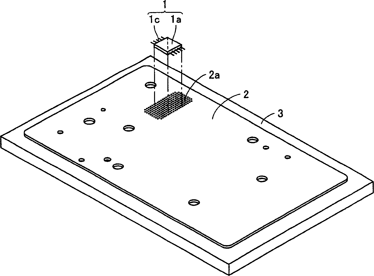
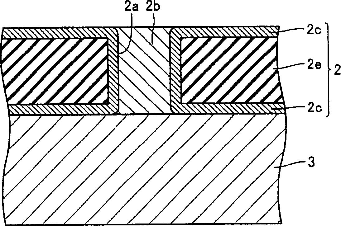
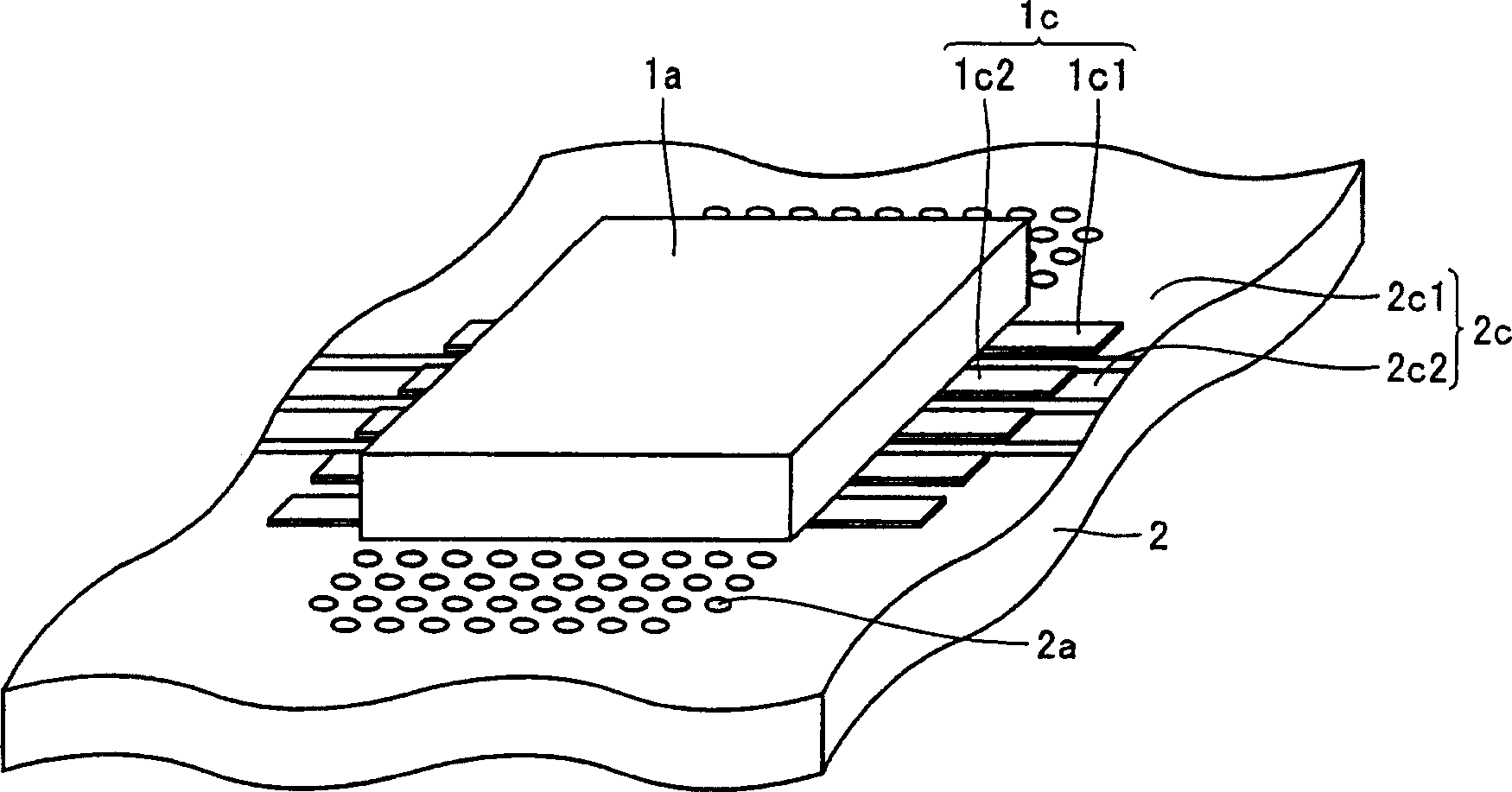
[0040] refer to Figures 1 to 6 , describes an MMIC-mounted substrate according to a first embodiment of the present invention. Such as figure 1 As shown, the substrate on which the MMIC is installed includes a double metal foil dielectric substrate 2 , an MMIC 1 and a metal chassis 3 . exist figure 1 In , for the convenience of description, the MMIC1 is shown as being separated from the double metal foil dielectric substrate 2 . MMIC1 is a surface mount high power amplifier and is disposed on one side of a double metal foil dielectric substrate 2 . A metal chassis 3 is attached to the other side of the dual metal foil dielectric substrate 2 . figure 2 yes figure 1 An enlarged partial cross-sectional view of the substrate on which the MMIC is mounted is shown. Such as figure 2 As shown, a double metal foil dielectric substrate 2 has copper foil patterns 2c formed as metal foil patterns on both sides of a dielectric substrate 2e. The double metal foil dielectric su...
no. 2 example
[0054] refer to Figures 7 to 9 , describes an MMIC-mounted substrate according to a second embodiment of the present invention. Such as Figure 7 As shown, the substrate on which the MMIC is mounted includes a double metal foil dielectric substrate 2 , an MMIC 1 , a metal chassis 3 and screws 4 . exist Figure 7 In , for the convenience of description, the MMIC1 is shown as being separated from the double metal foil dielectric substrate 2 . Screws 4 pass through the dual metal foil dielectric substrate 2 to connect to the metal chassis 3 . Figure 8 is the plan view before screw 4 connection. Such as Figure 8 As shown, the screw holes 2d are provided outside the area of the double metal foil dielectric substrate 2 occupied by the MMIC body 1a, and relatively close to the MMIC body 1a. Screw holes 2d are provided in the ground pattern 2c1.
[0055] Such as Figure 9 As shown, the screw 4 is screwed in the screw hole 2d. Screw 4 separates from MMIC1.
[0056] When ...
no. 3 example
[0063] refer to Figure 10 and 11 , describes an MMIC-mounted substrate according to a third embodiment of the present invention. Such as Figure 10 As shown, the substrate on which the MMIC is installed includes a double metal foil dielectric substrate 2 , an MMIC 1 , a metal chassis 3 , a cooling plate 5 and screws 4 . exist Figure 10 In , for the convenience of description, the MMIC1 is shown as being separated from the double metal foil dielectric substrate 2 . The heat dissipation plate 5 is in contact with the top surface of the MMIC 1 and has through holes for passing the screws 4 therethrough. The cooling plate 5 is preferably made of metal. The screw 4 passes through the cooling plate 5 and is fastened to press the cooling plate 5 onto the MMIC1 at the same time, as Figure 11 shown in the sectional view.
[0064] Other components and structures other than those discussed above are similar to those described with reference to the first and second embodiments, ...
PUM
 Abstract
Description
Claims
Application Information
 - R&D
- Intellectual Property
- Life Sciences
- Materials
- Tech Scout
- Unparalleled Data Quality
- Higher Quality Content
- 60% Fewer Hallucinations
Browse by: Latest US Patents, China's latest patents, Technical Efficacy Thesaurus, Application Domain, Technology Topic, Popular Technical Reports.
© 2025 PatSnap. All rights reserved.Legal|Privacy policy|Modern Slavery Act Transparency Statement|Sitemap|About US| Contact US: help@patsnap.com