Cutting tool head for a metal working tool

一种工具头、机床的技术,应用在工具头领域,能够解决多空间、占用等问题

Inactive Publication Date: 2005-06-08
SANDVIK INTELLECTUAL PROPERTY AB
View PDF0 Cites 10 Cited by
  • Summary
  • Abstract
  • Description
  • Claims
  • Application Information

AI Technical Summary

Problems solved by technology

The system is relatively space-intensive for the thin gripping edges of parting tools, since the hold-down device consists of relatively long pins

Method used


Image

  • Cutting tool head for a metal working tool
  • Cutting tool head for a metal working tool

Examples


Embodiment Construction

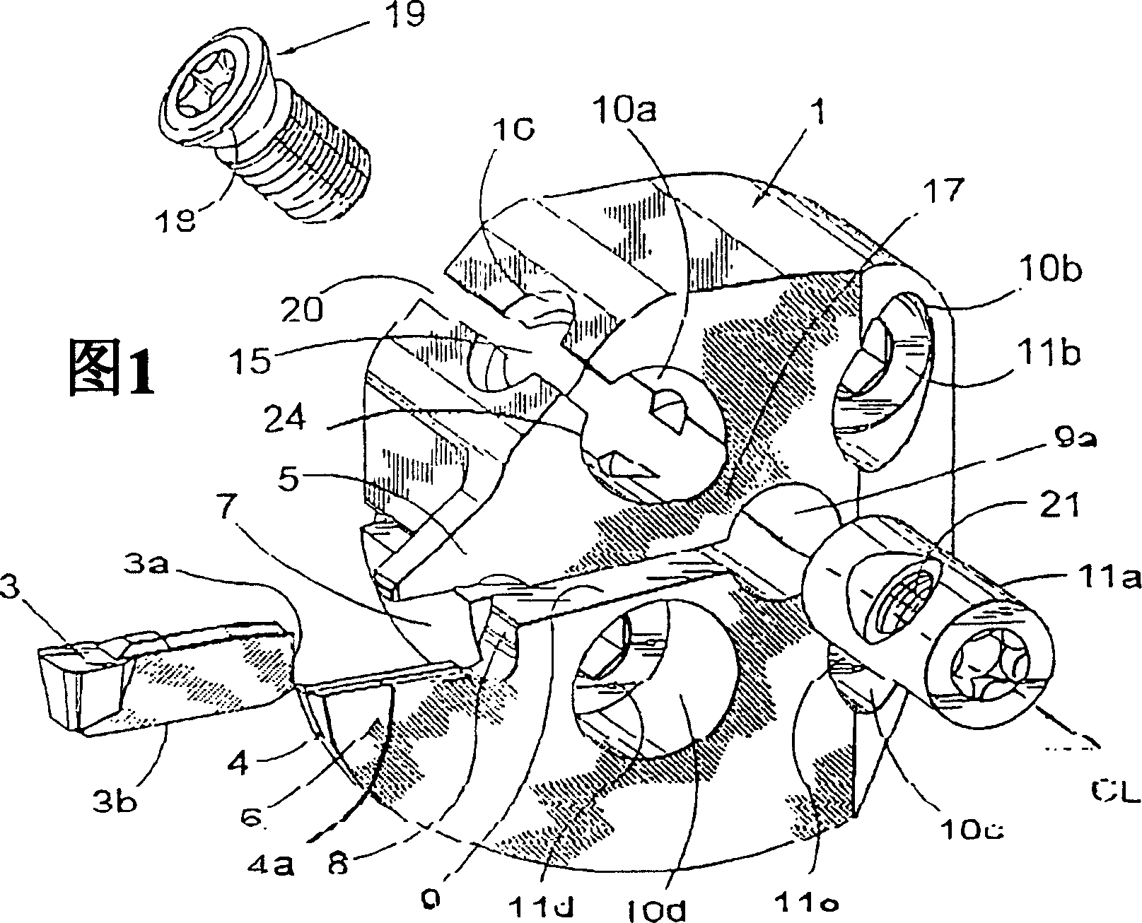
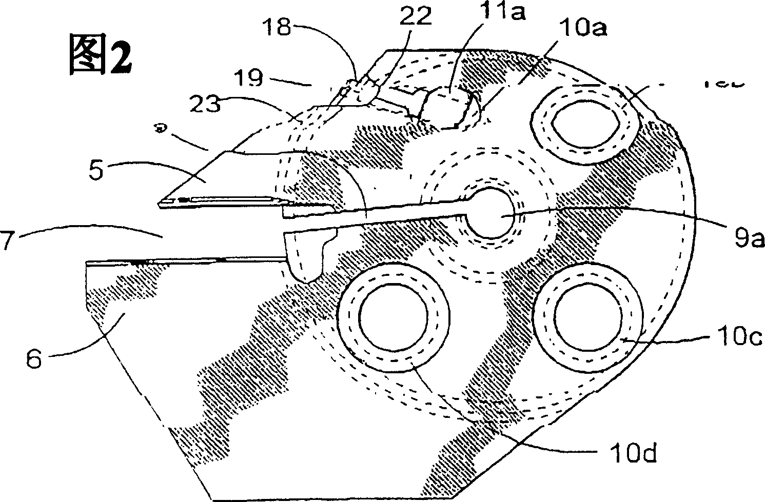
[0011] Fig. 1 shows a tool head for a metal removal machine tool according to a preferred embodiment of the present invention. The tool head includes a main holder 1 having a central hole 9a for engagement with a machine tool. The main clamp 1 has a blade clamp 4 connected thereto, which is formed in the shape of a forward transverse boss. Preferably, the master clamp is adapted to be connected to a machine tool, such as a multifunction lathe, by an engaging member suitable for the purpose. The front part of the insert holder 4, i.e. the front part of said forward transverse projection, is constituted by a blade-shaped part in which an insert pocket 7 in the form of a fixed pocket is provided to accommodate a cutting insert 3 for chip removal machining. . A blade pocket 7 is formed between a lower support portion 6 for supporting the blade 3 and an upper fixing portion 5 integrally formed with the lower support portion 6 , wherein the upper fixing portion 5 has a width small...


PUM


Abstract

The present invention is related to a tool head for chip removing metal machining tools having a cutting insert (3), comprising a basic holder (1) and an insert holder (4) connected therewith, which in the front portion thereof is formed with an insert pocket (7), which is formed between a lower support part (6) and an upper clamping portion (5). The upper clamping portion (5) is actuatable by means of a press arrangement into clamping surface engagement with the cutting insert (3), which is insertable into the insert pocket, the tool being formed with a slot (20) spaced-apart from the insert pocket. The press arrangement comprises a clamping screw (19), which is received in a bore (15) in the basic holder, and a nut roll (11a) adapted to receive the clamping screw, the nut roll being received in a recess (10a) in the basic holder. The recess (10a) is oriented perpendicularly to the longitudinal direction of the cutting insert and the insert pocket. Upon co-operation with the clamping screw (19) during tightening of the clamping screw, the nut roll (11a) is adapted to be imparted movement substantially in the axial direction of the clamping screw radially outwards, such that the nut roll is displaced into said slot (20) and thereby accomplishes such a deflection of the upper portion of the holder that a clamping of the cutting insert (3) is accomplished by this deflection. <IMAGE>

Description

technical field [0001] The present invention relates to a tool head for chip removal machining of metals. [0002] The tool head includes a main clamp and a blade clamp connected thereto. More specifically, the tool is suitable for machining operations known as parting and grooving. technical background [0003] Various couplings are already known in the field of chip removal for the realization of a torque-proof connection between different holders and adapters, but most commonly in various turning tools. For example, Swedish patent application 7813038-2 discloses a tool for parting and grooving using cooperating serrations with set screws as fixing means. In this case three screws are used to secure the adapter to the clamp, which means that the procedure for changing the blade is rather time consuming by first removing three relatively long screws and then tightening them after the blade has been changed. Furthermore, Swedish patent application 9004032-0 discloses a cu...

Claims


Application Information

Patent Timeline
Patent Type & Authority Applications(China)
IPC IPC(8): B23B29/00B23B27/00B23B27/04B23B29/04
CPCB23B27/04B23B29/043B23B2205/02B23B2220/123Y10T407/2288Y10T407/2282Y10T407/2286B23B29/00B23B27/00B23B29/04
Inventor 佩尔·艾戈瓦金·哈桑
Owner SANDVIK INTELLECTUAL PROPERTY AB
Why Eureka
Try Eureka