
Cutter apparatus for flat plate building material

A technology for building materials and cutting tools, applied in sawing machines, stone processing tools, wood processing appliances, etc., can solve the problems of power cost, complex structure, and large installation space requirements.

Inactive Publication Date: 2005-05-04
SHINYU CORP
View PDF6 Cites 4 Cited by
  • Summary
  • Abstract
  • Description
  • Claims
  • Application Information

AI Technical Summary

Problems solved by technology

[0016] Yet the off-the-shelf brick cutting device etc. shown in patent document 1-6, owing to need driving device, in order to move brick or cutter linearly, therefore in addition to driving electric cutter for cutting, also will spend power cost more, and structure Very complicated
In addition, when bricks or knives are moved manually without an electric drive mechanism, the workload is heavy
In addition, the existing brick cutting device, etc., adopts the method of fixing or moving the brick or the cutter horizontally, so the whole device becomes very large, and the installation space is also required to be large.

Method used


Image

  • Cutter apparatus for flat plate building material
  • Cutter apparatus for flat plate building material
  • Cutter apparatus for flat plate building material

Examples


Embodiment Construction

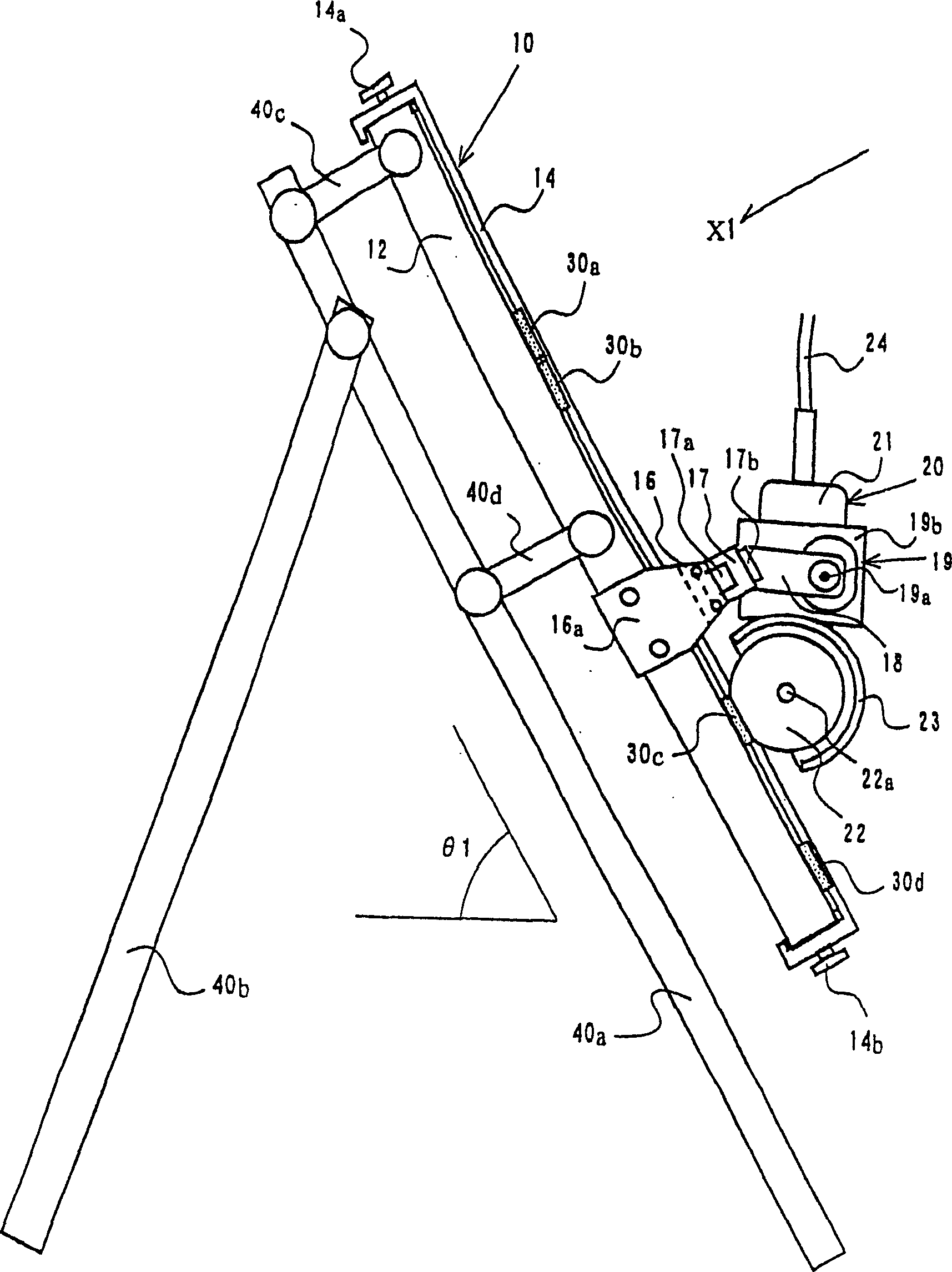
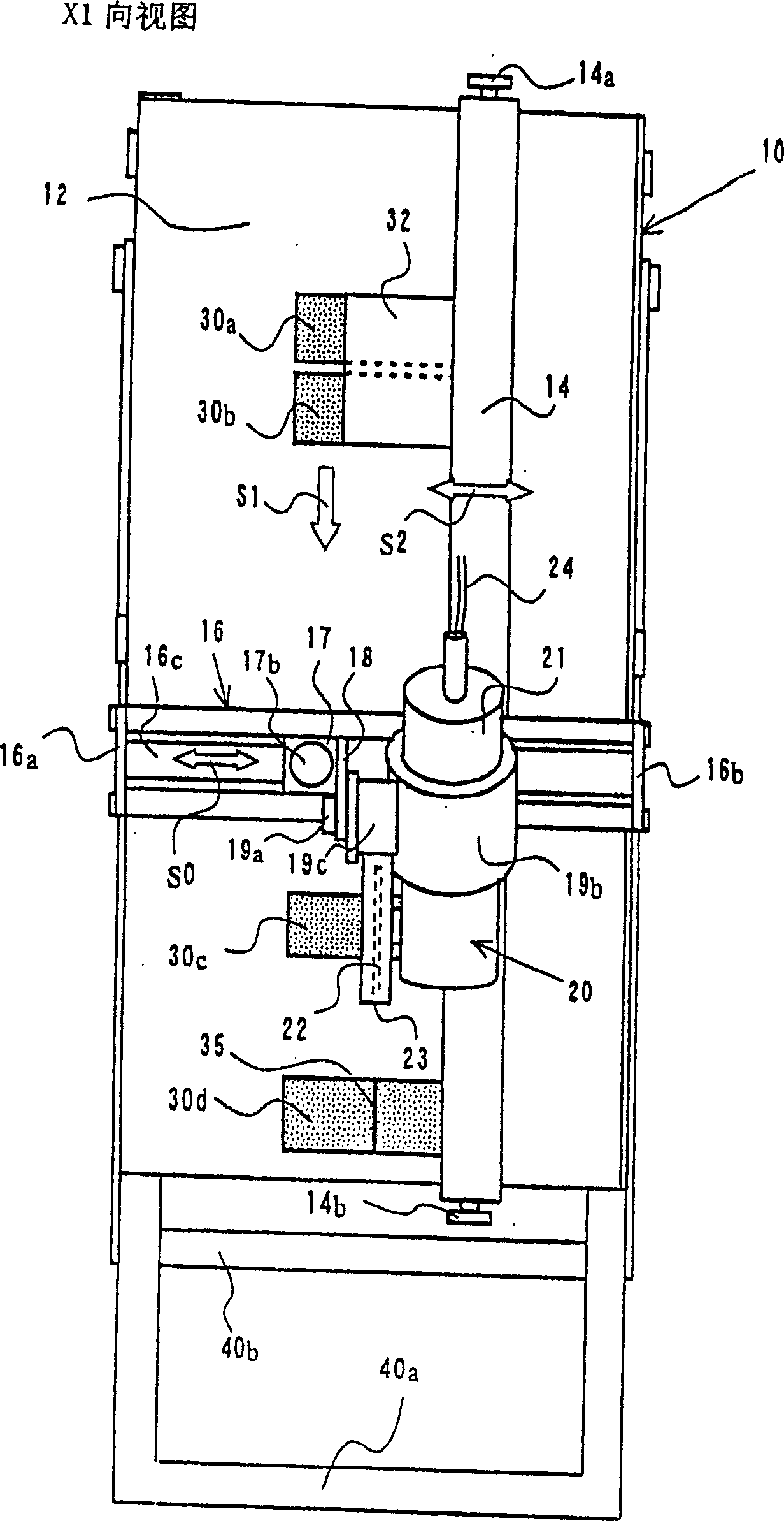
[0072] figure 1 It is a side view of a cutter device for flat building materials according to an embodiment of the present invention. figure 2 for along figure 1 The arrow X1 shown is a view in the X1 direction of the cutter device for flat building materials. The following will describe the case where the flat building material is ceramic tiles.

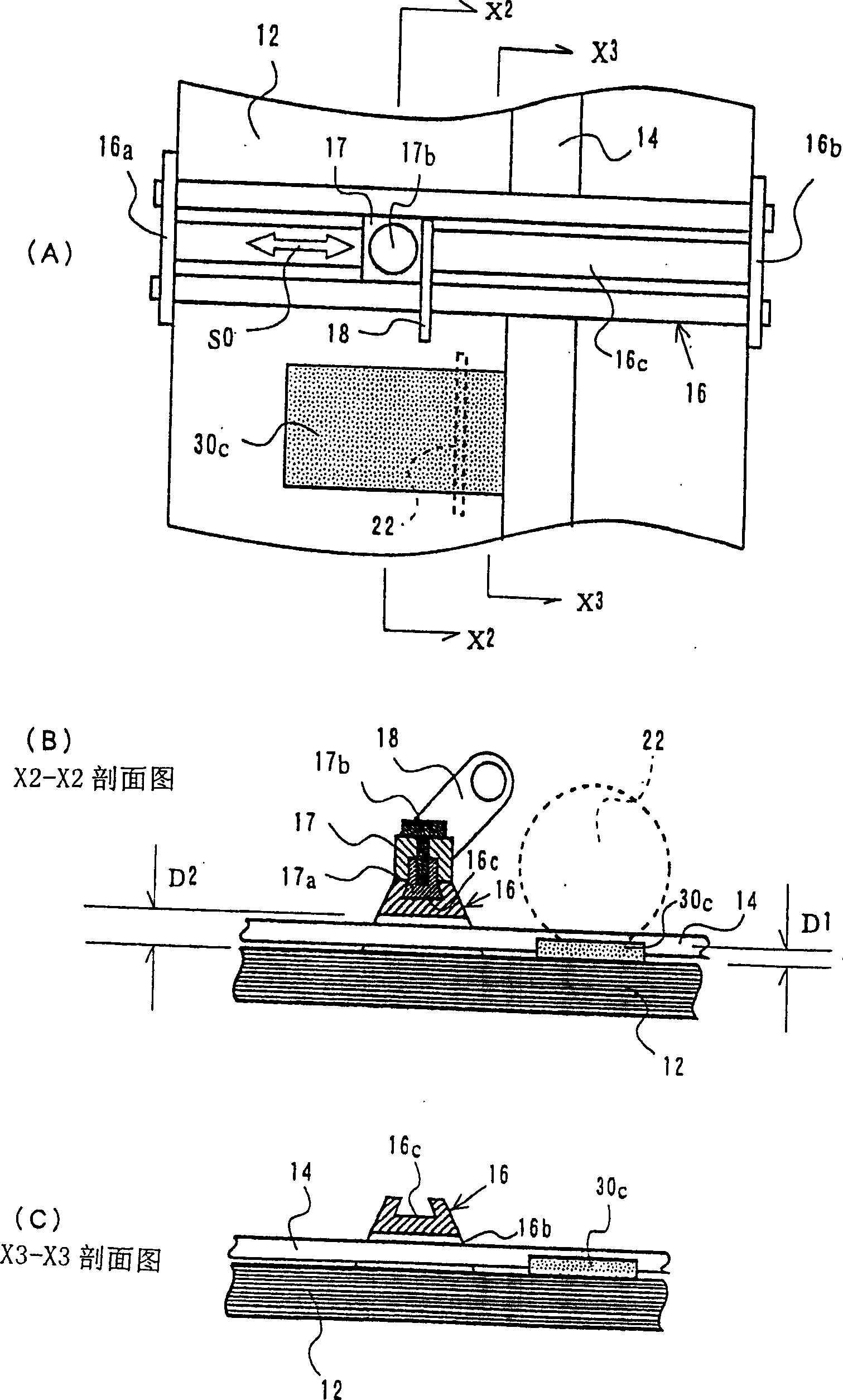
[0073] According to the cutter device 10 for flat building materials of the present invention, there is a cutter 20 provided with an inclined table 12 provided with an inclined surface and a rotary blade 22 for cutting the ceramic tiles 30a-30d that slide down from the inclined surface, and for setting the rotary blade 22 The tool fixing method of the fixed tool 20 at a certain height from the above-mentioned slope. The inclination angle of the slope is represented by θ1.

[0074] For the sake of safety, a rotary blade cover 23 is provided to cover the rotary blade 22 safely. A motor and the like for driving the rotary blade 2...


PUM


Abstract

The present invention provides a cutter device for flat building materials capable of rapidly cutting flat building materials such as ceramic tiles into arbitrary sizes. The knife device for flat building materials includes a knife with an inclined table provided with a slope, a rotary blade for cutting the flat building material sliding down the slope, and a knife fixing method for setting the rotary blade at a certain height from the slope. The tool fixing method has a tool guide rail erected between two ends of the inclined table, a movable support part movable along the tool guide rail, and a tool holder mounted on the movable support part and supporting the tool housing.

Description

technical field [0001] The present invention relates to a cutter device for flat building materials for cutting flat building materials such as ceramic tiles or forming incisions. Background technique [0002] Ready-made flat building materials such as inlaid bricks must be cut and processed to make it into the required size (vertical and horizontal dimensions) during construction. The simplest method, for example, is to draw a rough cutting line on the brick with a magic pen, fix the brick, and then operate a disc-shaped electric cutter to cut along the cutting line drawn by the magic pen. [0003] Adopt the existing brick cutting device etc. of automatic mechanism also have as shown in following patent documents 1-6 and its many structures. Most of them are composed of a disc-shaped electric cutter and a brick fixing method or a brick transporting method. For example, as shown in the following patent documents 2 and 5, the brick is fixed and the electric cutter is moved ...

Claims


Application Information

Patent Timeline
Patent Type & Authority Applications(China)
IPC IPC(8): B28D1/24B23D47/04B26D1/143B27B5/06B28D1/04
CPCB23D47/045B27B5/063B28D1/04Y10T83/7697Y10T83/869B26D1/143
Inventor 樋口正人
Owner SHINYU CORP
Learn More