
Fluorescent lamp, bulb shaped fluorescent lamp and light fixtures

A technology for fluorescent lamps and light bulbs, applied in lighting devices, independent lighting devices, lighting and heating equipment, etc., can solve the problem of reducing the beam of fluorescent lamps, achieve good beam increase, small set particle size, and inhibit the increase of BET specific surface area Effect

Inactive Publication Date: 2005-04-20
TOSHIBA LIGHTING & TECH CORP
View PDF0 Cites 3 Cited by
  • Summary
  • Abstract
  • Description
  • Claims
  • Application Information

AI Technical Summary

Problems solved by technology

Therefore, when using α-alumina as a binder, there is also a problem that the overall beam of the fluorescent lamp is reduced

Method used


Image

  • Fluorescent lamp, bulb shaped fluorescent lamp and light fixtures
  • Fluorescent lamp, bulb shaped fluorescent lamp and light fixtures
  • Fluorescent lamp, bulb shaped fluorescent lamp and light fixtures

Examples


Embodiment Construction

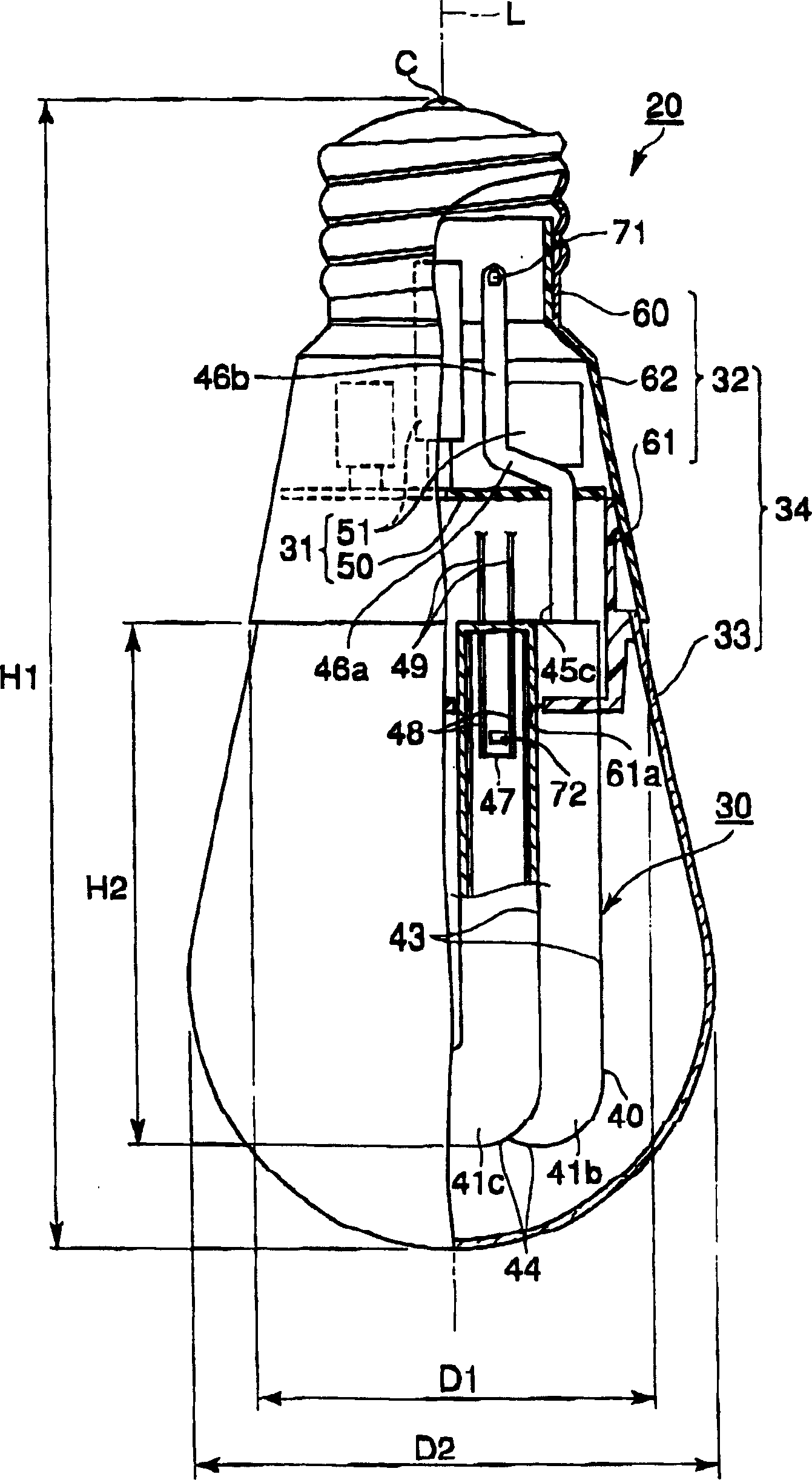
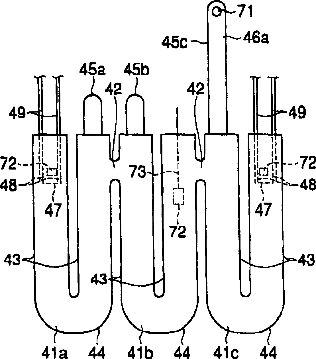
[0072] Hereinafter, refer to the Figure 1-Figure 3 , the first embodiment of the present invention will be described.

[0073] Such as figure 1 As shown, the bulb-shaped fluorescent lamp 20 has triple U-shaped fluorescent lamps 30, a lighting device 31 having a base 50 and electronic components 51, a cover 32 having a base 60 and a holder 61 as a holding part, and a bulb 33. The housing 34 composed of the cover 32 and the bulb 33 is formed to have an outer shape close to the standard size of a general lighting bulb such as an incandescent bulb with a rated power equivalent to 40W. That is to say, the height H1 including the lamp base 60 is about 110-125 [mm], the diameter, that is, the outer diameter D1 of the bulb 33 is about 50-60 [mm], and the outer diameter of the cover body 32 is about 40 [mm]. In addition, the so-called light bulbs for general lighting are light bulbs standardized in accordance with JISC7501.

[0074] The fluorescent lamp 30 includes a light-transmi...


PUM


Abstract

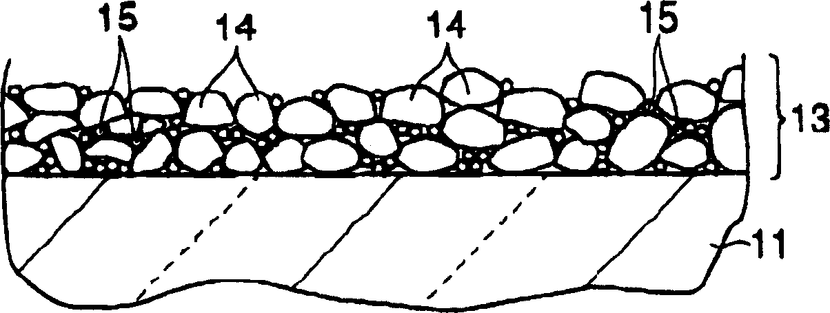
The present invention provides a fluorescent lamp which can suppress the reduction of the fluorescent film from the glass on the luminous tube and the total beam, and can obtain a good beam increasing characteristic. A light-transmitting luminous tube (40) and a fluorescent film (13) arranged inside the luminous tube (40). The fluorescent film (13) contains spherical metal oxide (15) particles. The spherical metal oxide (15) is suitable as a binder, and therefore, the peeling of the fluorescent film (13) from the light emitting tube (40) can be suppressed. In addition, the surface physical adsorption force of the spherical metal oxide (15) is not strong, so good beam growth characteristics can be obtained.

Description

technical field [0001] The present invention relates to a fluorescent lamp, a bulb-shaped fluorescent lamp, and a lighting fixture. Background technique [0002] Fluorescent thin films are usually sputtered and adhered to the inside of the luminous tubes that fluorescent lamps have. However, the fluorescent film is easily peeled off from the luminous tube due to impact or the like. In order to suppress such troubles, add a small amount (about several wt% relative to the weight of the fluorescent substance) of the fluorescent film, and the BET specific surface area is 2-20 [m 2 / g] of α-alumina as a binder (for example, see Patent Document 1). [0003] In addition, it is also known to use α-alumina having pipe diameters of major diameter a and minor diameter b of 0.5≦b / a≦1.0 as the metal oxide fine particles (for example, see Patent Document 2). [0004] In addition, it is also known to add γ-alumina having a smaller particle size than α-alumina and a larger BET specific s...

Claims


Application Information

Patent Timeline
IPC IPC(8): F21S6/00H01J61/24H01J61/44H01J61/54
Inventor 中村光纪田村畅宏泉昌裕池田敏幸高原雄一郎渡边美保
Owner TOSHIBA LIGHTING & TECH CORP
Learn More