
Door Lock assembly

A door lock and latch technology, which is applied in washing devices, other washing machines, textiles and paper making, etc., can solve the problems that the door cannot be opened, the door is frequently opened or closed, and the operation is inconvenient, so as to reduce production costs and facilitate assembly. , the effect of simple components

Inactive Publication Date: 2005-03-30
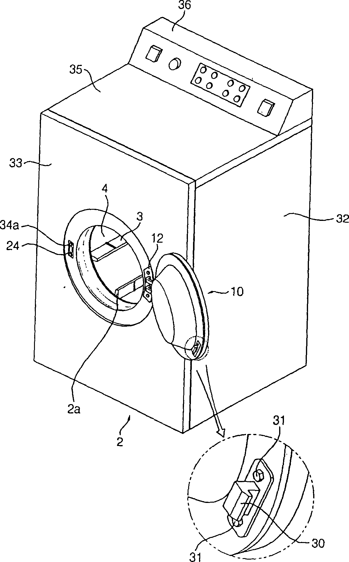
LG ELECTRONICS (TIANJIN) APPLIANCES CO LTD
View PDF0 Cites 24 Cited by
  • Summary
  • Abstract
  • Description
  • Claims
  • Application Information

AI Technical Summary

Problems solved by technology

[0008] On the one hand, when the door is closed and power is input to the door lock switch, the door lock switch prevents the separation of the hook so that the door cannot be opened.
[0009] However, the drying machine using the prior art is different from the washing machine. Since there is no washing water, the user will arbitrarily open and close the door during the operation of the drying machine to add wet laundry with water, or the user to confirm When the clothes are drying, the door will be opened or closed frequently
Because the conventional door lock device has the same structure as that of the washing machine, it is inconvenient to open and close the door, and it also requires a lot of force.

Method used


Image

  • Door Lock assembly
  • Door Lock assembly
  • Door Lock assembly

Examples


Embodiment Construction

[0031] The present invention will be described in detail below with reference to the drawings and examples.

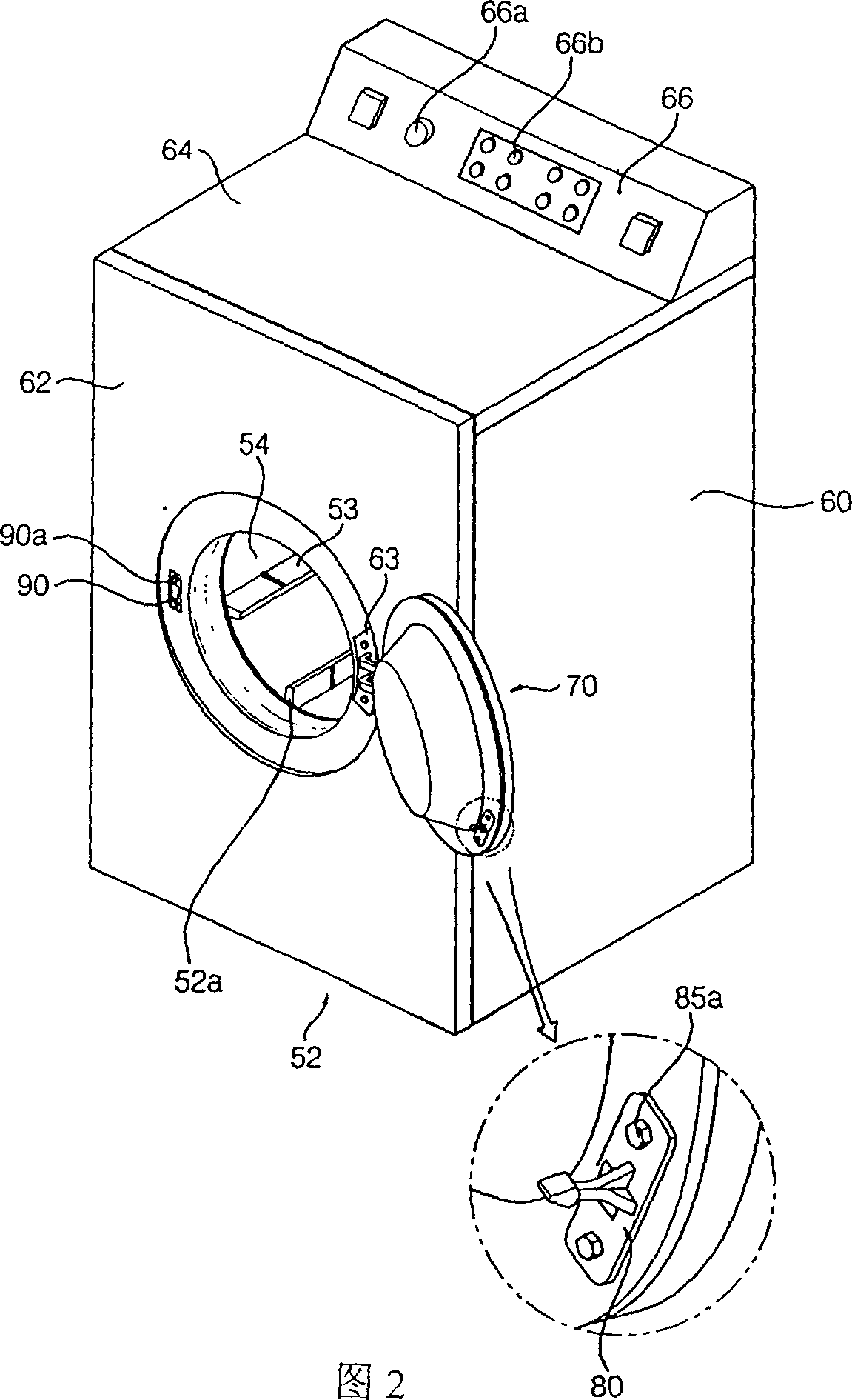
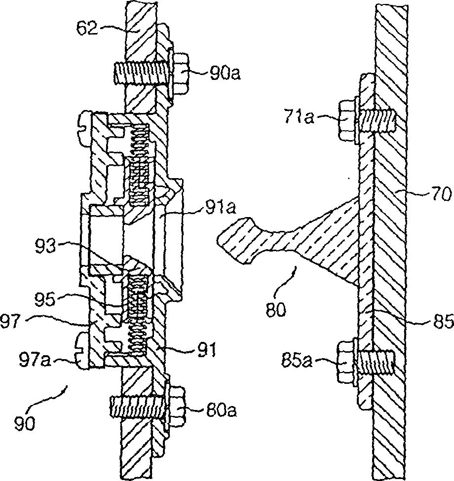
[0032] Fig. 2 is a schematic diagram of the appearance structure of the dryer of the present invention. As shown in Figure 2, the drying machine in the embodiment of the present invention includes a casing (52) with a washing access hole (52a) formed in the center of the front to form an appearance, installed inside the casing (52), facing The drum (54) with openings in the front and rear directions to accommodate the laundry, and a lifter (53) that can be lifted and put down the laundry is rotatably installed on the inner peripheral surface of the drum (54), to produce the laundry that is necessary for drying. A heater (not shown) for drying hot air, and a drum (54) rotated by a motor (not shown) that generates a driving force are used to block the laundry inlet and outlet holes (52a) during the operation of the dryer. Inside, a door (70) is rotatably attached to the...


PUM


Abstract

A lock device of dryer on washer consists of box body, door with hook, bump lock with support object having hook, hook bulge at hook top, front tilting portion formed at front of hook bulge for pushing support object away to lead it in at time of door closing, back tilting portion at back of front tilting portion for pushing support object away to lead in out at time of door opening.

Description

technical field [0001] The present invention relates to a securing device, or locking device, for a door of a dryer which prevents the door from being dislodged indiscriminately. In more detail, it is a door lock device that controls the door to disengage at will. Background technique [0002] In general, a washing machine is a device that removes dirt by applying appropriate detergent and mechanical force to washing, spin-drying, and dehydration processes. Recently, there have been developments and use of dryers with combined drying capabilities that add drying capabilities to laundry in addition to washing capabilities, and dryers that specialize in drying capabilities. [0003] figure 1 It is a schematic diagram of the appearance structure of an ordinary dryer. [0004] The conventional drying machine is formed with the access hole (2a) for putting in and taking out the laundry in the front of the casing (2), and behind the laundry access hole (2a) of the casing (2), i...

Claims


Application Information

Patent Timeline
Patent Type & Authority Applications(China)
IPC IPC(8): D06F37/28E05C19/06
Inventor 黄圣纪
Owner LG ELECTRONICS (TIANJIN) APPLIANCES CO LTD
Learn More