
Apparatus for compensating for speed error of motor

A speed error, compensation motor technology, used in the control of the speed or torque of the motor, the angular single-axis angular velocity control of the AC motor, and the control of the electromechanical transmission device.

Inactive Publication Date: 2005-03-23
LG ELECTRONICS INC
View PDF1 Cites 14 Cited by
  • Summary
  • Abstract
  • Description
  • Claims
  • Application Information

AI Technical Summary

Problems solved by technology

[0010] However, if Figure 4 As shown, according to the method of using the look-up table storing the previously calculated compensation values, the torque of the motor can only be compensated at the rotor position where the compensation values ​​stored in the look-up table have been calculated.

Method used


Image

  • Apparatus for compensating for speed error of motor
  • Apparatus for compensating for speed error of motor
  • Apparatus for compensating for speed error of motor

Examples


Embodiment Construction

[0027] Preferred embodiments of the present invention will be described in detail below with reference to the accompanying drawings.

[0028] The following will refer to Figure 5A to Figure 7 A device for compensating the speed error of a motor in detail, which can reduce vibration and noise caused by load characteristics, and realizes its function by dividing the rotation area equivalent to a complete rotation of the rotor of the motor into a number of predetermined The turning area compares the reference speed and the previous estimated speed in each divided turning area, decides each speed compensation value, and compensates for a speed error between the reference speed and the current estimated speed based on each speed compensation value.

[0029] Figures 5A to 5C illustrate the principle of speed error compensation according to the present invention. That is to say, FIG. 5A to FIG. 5C show a method that divides the rotation area corresponding to one complete rotation o...


PUM


Abstract

The present invention discloses an apparatus for compensating for a speed error of a motor which can reduce a speed ripple of the motor resulting from load characteristics, and which also can reduce vibrations and noises. The apparatus for compensating for the speed error of the motor divides a rotational section corresponding to one complete revolution of a rotor of the motor into a plurality of preset rotational sections, determines a speed compensation value in each divided rotational section on the basis of a difference value between a reference speed and a previous estimated speed, and compensates for the speed error of the motor on the basis of the speed compensation value.

Description

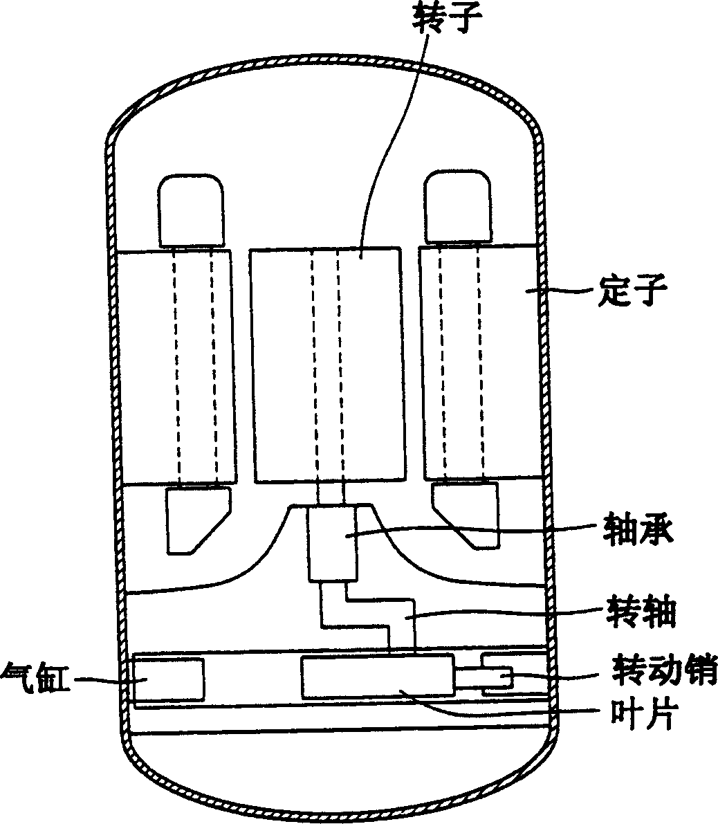
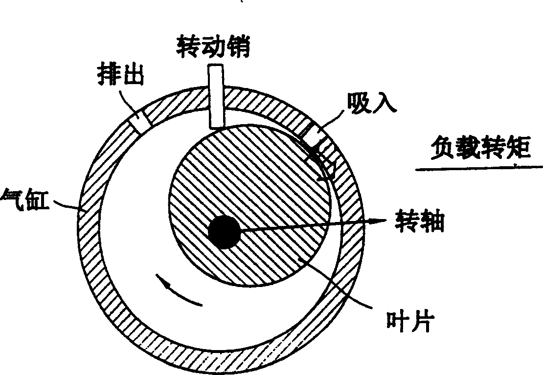
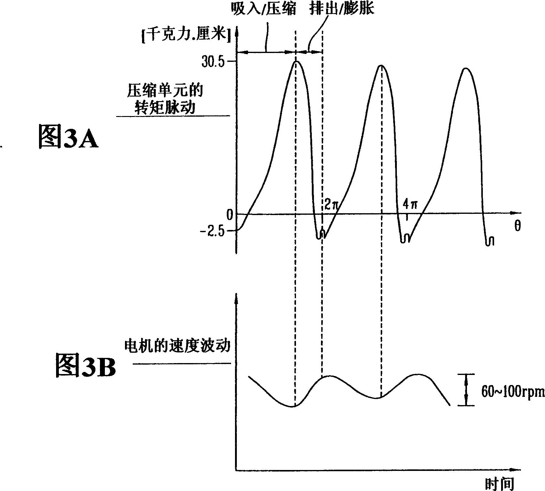
technical field [0001] The present invention relates to motors, in particular to a device for compensating motor speed errors. Background technique [0002] In general, the load characteristics of motor-driven compressors vary depending on the type of compression. In particular, when a single-cylinder rotary compressor with driving torque pulsation is rotated according to the load characteristics of the compressor, the torque pulsation of the compressor increases, and due to the increase in the torque pulsation of the compressor, the speed of the motor Increased volatility. That is, when a load having a torque pulsation component such as a single-cylinder rotary compressor is combined with a motor, the torque pulsation of the load generates speed fluctuations. [0003] figure 1 A conventional single-cylinder rotary compressor is illustrated schematically, the compression unit of a single-cylinder rotary compressor (see figure 2 ) is combined with the rotor of the motor ...

Claims


Application Information

Patent Timeline
Patent Type & Authority Applications(China)
IPC IPC(8): F04C28/08F04B49/06F04C18/356F04C28/28H02P6/06H02P6/08H02P6/10H02P6/17H02P6/28H02P21/00H02P21/05H02P21/14H02P21/22H02P23/04H02P23/16H02P27/04H02P27/08
CPCF04C28/28H02P21/146H02P21/0042H02P23/0059F04C2270/80H02P21/05H02P23/0045H02P23/16H02P23/186H02P21/26H02P21/18H02P21/14
Inventor 吴在胤郑澾浩
Owner LG ELECTRONICS INC
Learn More