Multi-lead-screw parallel drive device

A driving device and lead screw technology, which is applied in the direction of transmission, belt/chain/gear, mechanical equipment, etc., can solve the problems of decreasing the accuracy of the mechanical device, increasing the local stress and working strength of the parts, and reducing the mechanical performance of the device. Low manufacturing accuracy and installation accuracy, lower manufacturing costs, and good dynamic performance

Active Publication Date: 2014-07-23
BEIJING AEROSPACE AUTOMATIC CONTROL RES INST +1
View PDF7 Cites 5 Cited by
  • Summary
  • Abstract
  • Description
  • Claims
  • Application Information

AI Technical Summary

Problems solved by technology

However, the traditional lead screw parallel drive is mostly simply to place two screw nut mechanisms in parallel, and fix the two nuts with a slider at the same time to drive the slider to move.
However, due to deviations in the manufacture and installation of lead screw nuts, even two lead screws of the same type cannot guarantee that their various parameters are exactly the same, and it is impossible to ensure that the two lead screws are completely parallel when installed, resulting in parallel drive of the lead screws. This kind of interference causes abnormal deformation of the parts of the mechanism, increases the local stress and working strength of the parts, increases the wear of the parts, causes the precision of the mechanical device to decrease, and even causes direct jamming, making the mechanical device invalid
At present, the lead screw driven in parallel by some devices uses one end fixed and one end floating support. Although the use of floating support can reduce the interference phenomenon of the lead screw drive to a certain extent, it cannot completely eliminate the interference.
Moreover, the floating support itself has poor stiffness, poor dynamic performance, and poor bearing capacity, which greatly reduces the mechanical properties of the device
After searching the existing technical literature, it is found that the patent publication number CN1472451A "Redundant Input Driver and Its Application" uses a parallel four-bar mechanism to solve the problem of uneven force on the screw during movement, but this Although the device eliminates the problem of uneven force on the screw to a certain extent, it does not solve the interference problem of the parallel screw in the process, and the device of this patent can only solve the load on the screw within a small range. The problem of uneven force, because the relative rotation of the two screw nuts cannot exceed half a circle, the application is greatly restricted

Method used


Image

  • Multi-lead-screw parallel drive device
  • Multi-lead-screw parallel drive device

Examples


Embodiment 1

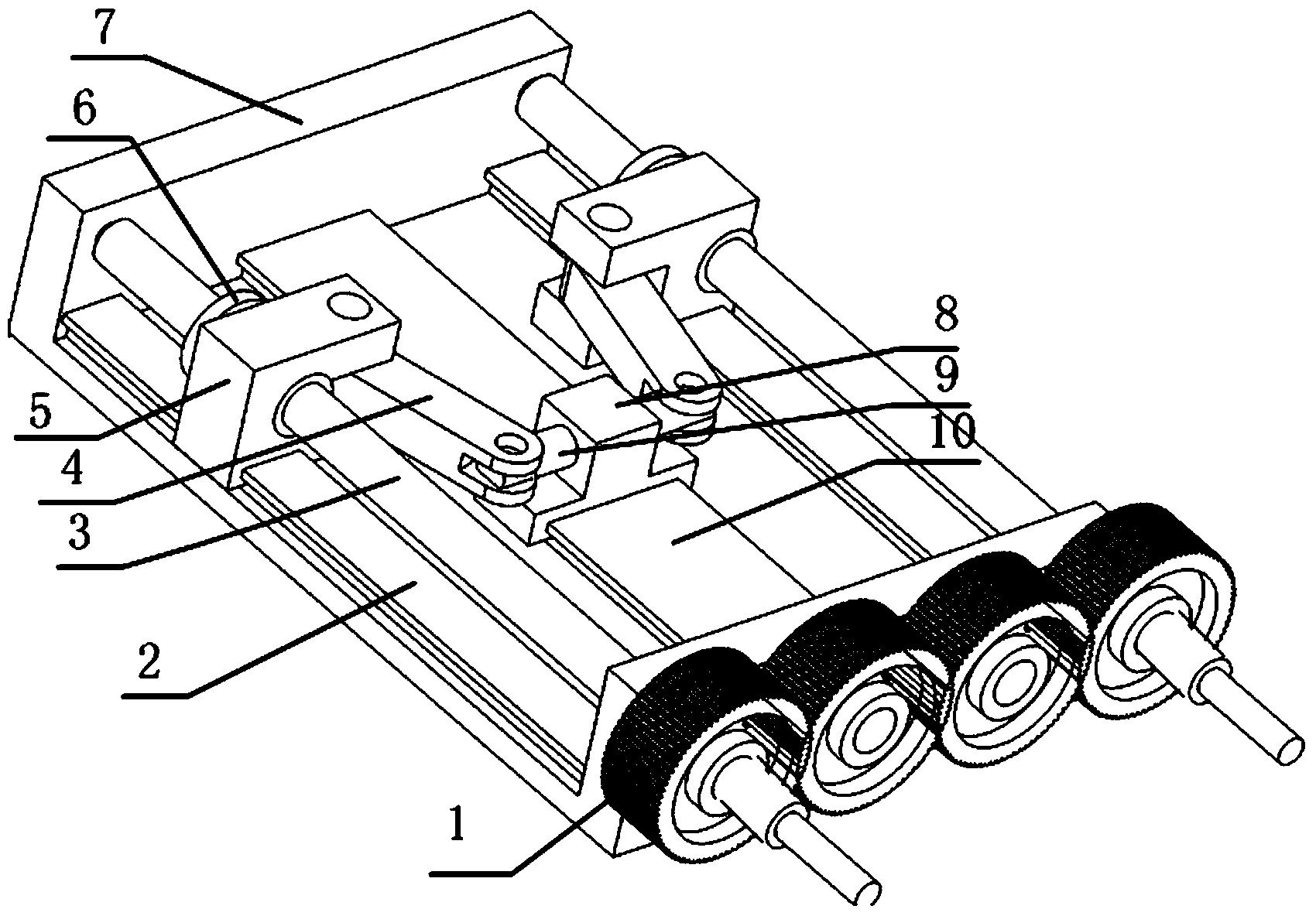
[0014] like figure 1 As shown, the device includes four gears 1, first-stage slider guide rail 2, lead screw 3, first-stage connecting rod 4, first-stage slider 5, lead screw nut 6, frame 7, second-stage slide Block 8, first level slide bar 9 and second level guide rail 10;

[0015] There are two first-stage slider guide rails 2, leading screws 3, first-stage connecting rods 4, first-stage sliders 5, and leading screw nuts 6;

[0016] Two lead screws 3 are installed on both sides of the frame 7, and a lead screw nut 6 is respectively installed on the two lead screws 3;

[0017] Two first-level slider guide rails 2 are fixed on both sides of the frame 7 and are located directly below the lead screw 3; the two first-level slider guide rails 2 are parallel to the respective upper lead screw 3;

[0018] The two first-stage sliders 5 are respectively fixedly mounted on the lead screw nuts 6;

[0019] When the lead screw 3 rotates, the lead screw nut 6 drives the first-stage slid...

Embodiment 2

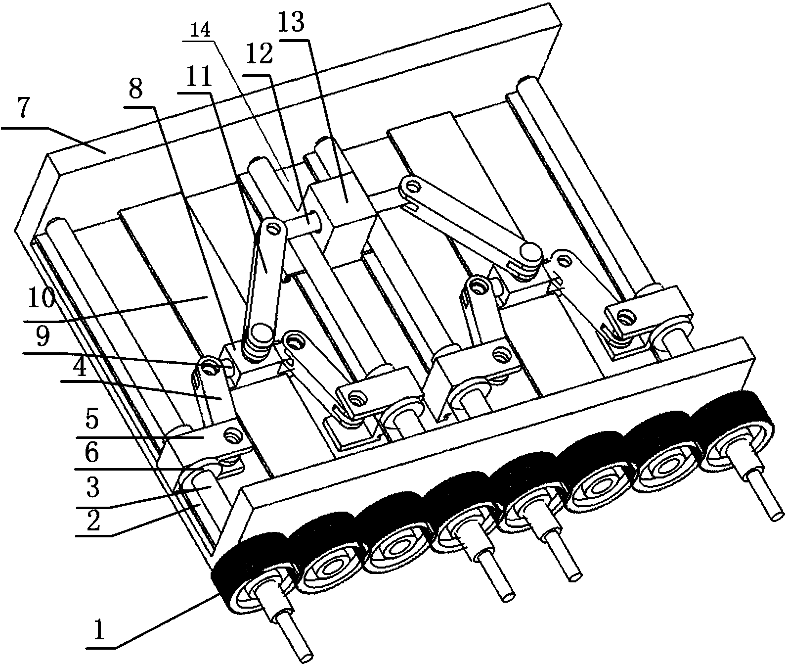
[0031] The device in this embodiment includes two sets of devices in Embodiment 1, the second-level connecting rod 11, the second-level sliding rod 12, the third-level sliding block 13 and the third-level guide rail 14;

[0032] The second-stage connecting rod 11, the second-stage slide bar 12, and the third-stage slide block 13 jointly constitute a coordinating rod device;

[0033] The third level slide block 13 is installed on the third level guide rail 14;

[0034] The second stage slide bar 12 passes through the third stage slide block 13, and the second stage slide bar 12 can slide along the axial direction of the second stage slide bar 12 relative to the third stage slide bar 13, and can also slide around the second stage. The axis of the rod 12 rotates, and the two form a cylindrical pair connection (when the installation plane of the two lead screws is parallel to the installation plane of the third-level guide rail 14, the second-level slide rod 12 and the third-level...


PUM


Abstract

The invention relates to a multi-lead-screw parallel drive device, and belongs to the technical field of mechanical engineering. The device comprises a gear for coordinating the rotating speed of lead screws, more than one pair of parallel lead screws, nuts, nut sliding blocks, linear guide rails, a coordinating rod device and a bearing sliding block, the nuts and the nut sliding blocks are matched with the lead screws, and the linear guide rails are matched with the sliding blocks to be used. The interference phenomenon cannot occur, and jamming caused by low precision of manufacturing and mounting is avoided. The lead screws are fixedly supported, rigidity is large, and the dynamic performance is good. Bearing sliding block errors caused by the motion error of a single lead screw can be reduced through a coordinating mechanism, and precision is improved. Rigid impacts are avoided in the motion process of the whole mechanism, and speed fluctuation of load sliding blocks is far lower than that of the nuts. The mechanism can be expanded, the number of the lead screws can be increased, the number of the lead screws can be two or four or eight or 2N, and the larger the number of the lead screws is, the higher the bearing capacity is, the rigidity is larger, and the speed fluctuation of the sliding blocks is smaller.

Description

technical field [0001] The invention relates to a multi-screw parallel driving device, which belongs to the technical field of mechanical engineering. Background technique [0002] The parallel drive mechanism is a mechanism in which two or more drive units are arranged in parallel to complete mechanical motion together. Using a parallel mechanism can improve the rigidity of the mechanical system, increase the load-carrying capacity of the mechanical device, and have a series of advantages such as high motion precision and good dynamic performance. Therefore, it is an important part of heavy equipment and is widely used in heavy simulation equipment and heavy processing equipment. [0003] Multi-screw parallel drive is to use two or more screw to drive a moving part at the same time, so as to share a total driving force to multiple driving screws. Through the parallel drive of multiple lead screws, the required power of a single motor can be reduced, the overall rigidity o...

Claims


Application Information

Patent Timeline
IPC IPC(8): F16H37/12
CPCF16H25/02
Inventor 王国涛杨丽杰白宇裴圣旺
Owner BEIJING AEROSPACE AUTOMATIC CONTROL RES INST
Why Eureka
Try Eureka