
Magnetic current changeing dumper of integrated related speed sensing function and method of adaptive damping

A magneto-rheological damper and relative speed technology, which is applied in the direction of shock absorbers, shock absorbers, springs/shock absorbers, etc., can solve the problem of affecting the overall reliability and stability of the vibration control system, increasing the cost of the vibration control system and Structural complexity, shortening the service life of the system, etc., to achieve the effect of improving adaptive performance, improving adaptability, and reducing system cost

Inactive Publication Date: 2005-03-23
CHONGQING UNIV
View PDF0 Cites 28 Cited by
  • Summary
  • Abstract
  • Description
  • Claims
  • Application Information

AI Technical Summary

Problems solved by technology

No matter which sensing method is used, the separately configured sensors not only increase the cost and structural complexity of the entire vibration control system, but also the sensors directly exposed to the external environment are easily affected by the external environment (such as mechanical collision, water seepage, oil seepage, etc.). Electromagnetic waves, etc.) interference or even damage, thus affecting the overall reliability and stability of the vibration control system, shortening the service life of the system

Method used


Image

  • Magnetic current changeing dumper of integrated related speed sensing function and method of adaptive damping
  • Magnetic current changeing dumper of integrated related speed sensing function and method of adaptive damping
  • Magnetic current changeing dumper of integrated related speed sensing function and method of adaptive damping

Examples


Embodiment Construction

[0032] The specific structure of the present invention and the parallel working process of realizing vibration sensing and damping are described below in conjunction with the embodiments and drawings.

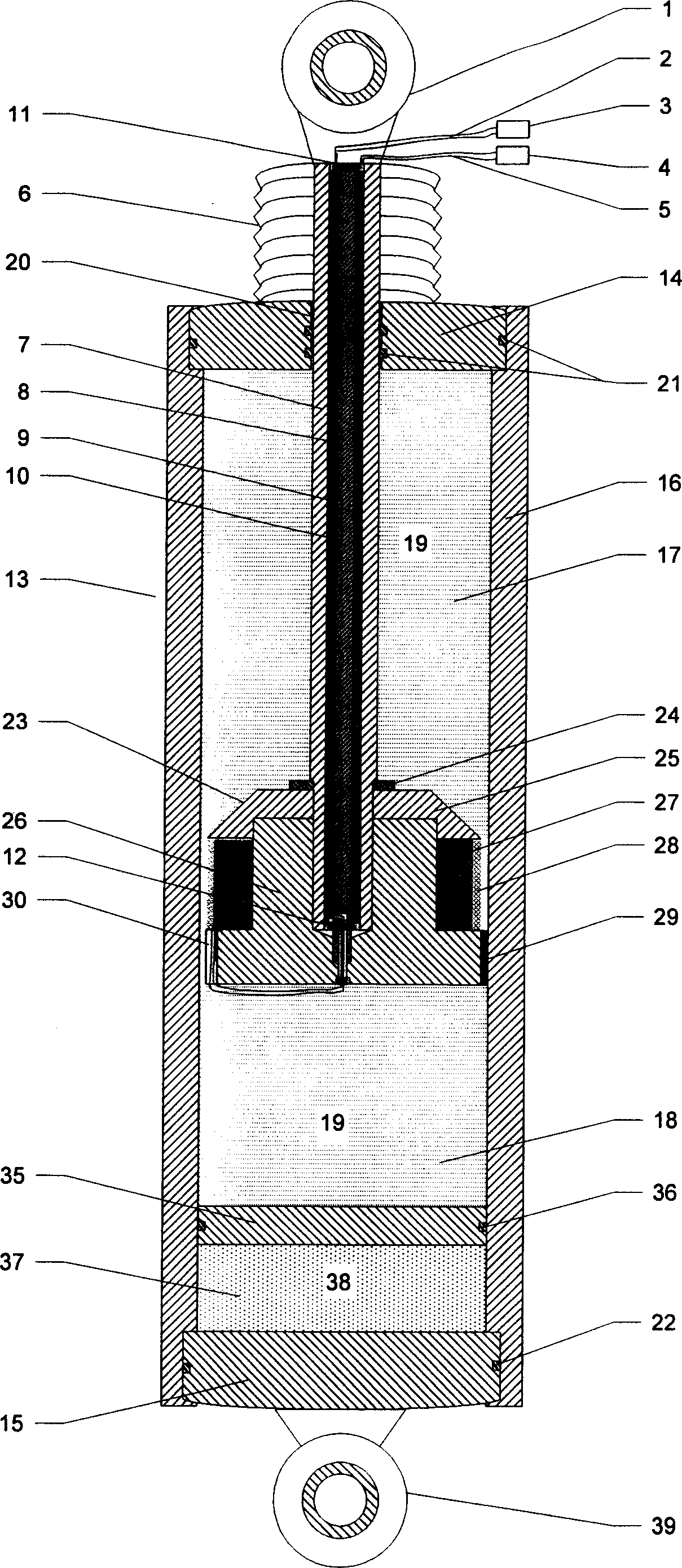
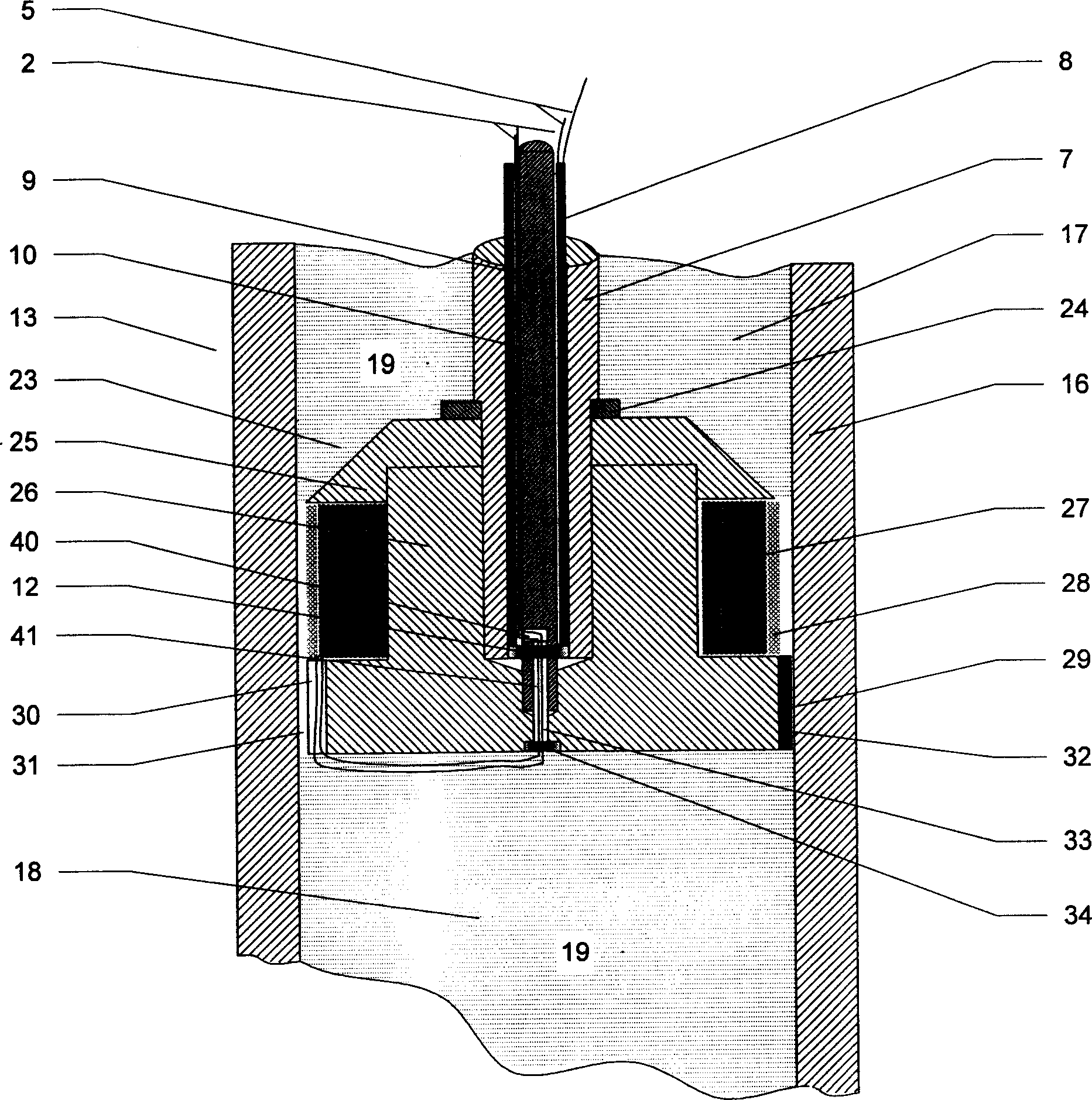
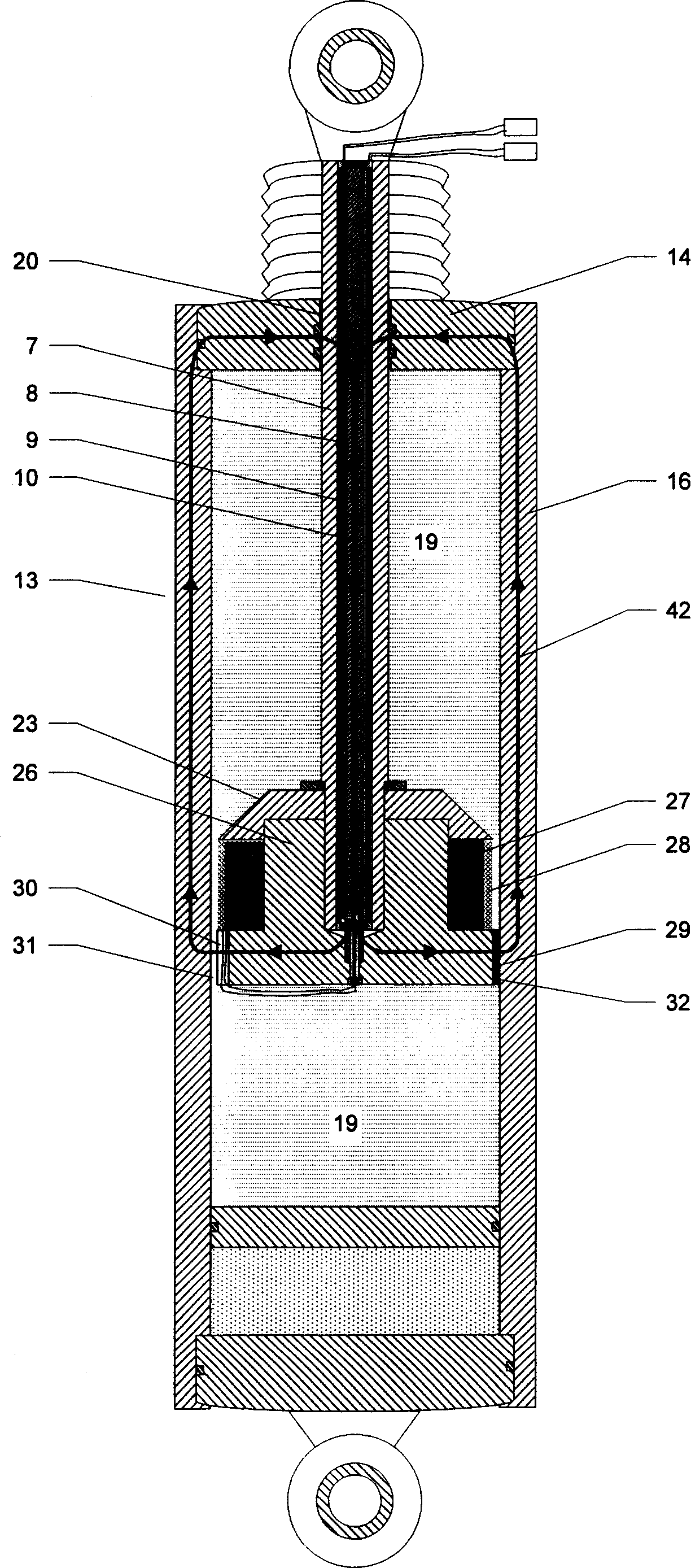
[0033] refer to figure 1 , figure 2 , an MR damper with integrated relative speed sensing function mainly includes a cylinder body 13, a magnetorheological fluid 19 installed in the cylinder body, a dust cover 6, a piston rod 7, a piston head 23, a sliding piston 35, a storage tank Parts such as the induction coil 8 in the energy device 37, the excitation coil 27 on the piston head, and the piston rod.

[0034] The cylinder block 13 of the damper is mainly composed of a cylinder barrel 16 with high magnetic permeability, an upper end cover 14 (through one end of the piston rod) and a lower end cover 15 with extremely low magnetic permeability.

[0035] The piston rod 7 of the damper is formed by processing low magnetic permeability material. The two ends of the piston rod ar...


PUM


Abstract

A self-adapting vibration reduction method and a magnetic rheology damper which has integration relative velocity conversion function. The damper is made up of cylinder body, magnetic rheology liquid, exciting coil on the piston head, induction coil in the piston rod, accumulator, and dirt shroud, and so on; the exciting coil and the induction coil are constituted a active magnetoelectricity type relative velocity transducer, it integrates the magnetic rheology damper structure to a unit. Its vibration reduction method is that exciting coil is loaded a medium-low frequency voltage sign as the transducer's exciting coil detection signal, common frequency alternating magnetic field which is produced by the method is formed to a closure work magnetic loop in the damper structure; axial direction relative motion between the piston of magnetic rheology damper and cylinder body make magnetic linkage of the induction coil occur to correspond change and induced obtain conversion output signal which reflects the axial direction relative motion; according to the conversion signal, controller self-adapting adjusts the drive current which is overlap on the exciting coil by current drive to control the magnetic field strength of the exciting coil to realize the self-adapting vibration reduction of the magnetic rheology.

Description

technical field [0001] The invention relates to a magneto-rheological damping device, in particular to a magneto-rheological damper integrated with a relative speed sensing function and a corresponding self-adaptive damping method. Background technique [0002] Vibration is a common physical phenomenon. With the continuous progress of human society and the continuous development of science and technology, vibration problems in the fields of transportation, national defense, machining, building structures, and scientific research have attracted increasing attention. For a long time, in order to effectively overcome and avoid various unfavorable vibrations, passive, active and semi-active vibration control systems have been proposed successively. In recent years, due to the successive appearance of magnetorheological fluids and magnetorheological dampers (abbreviated as MR dampers) and their continuous improvement in performance, semi-active vibration reduction systems based o...

Claims


Application Information

Patent Timeline
IPC IPC(8): F16F9/53F16F15/03
CPCF16F9/535
Inventor 王代华赖大坤
Owner CHONGQING UNIV
Learn More