
Loop antenna device

A technology of loop antenna and short-circuit loop, which is applied in the direction of loop antenna, shielded loop antenna, antenna, etc., and can solve the problem that the desired balance of the loop antenna unit is easily damaged

Inactive Publication Date: 2005-03-16
SEIKO EPSON CORP +1
View PDF2 Cites 4 Cited by
  • Summary
  • Abstract
  • Description
  • Claims
  • Application Information

AI Technical Summary

Problems solved by technology

[0016] In short, trying to assemble multiple loop antenna elements together to adjust the sum of the magnetic moments to "0" still encounters the problem that the desired balance between the loop antenna elements is easily disrupted in actual use

Method used


Image

  • Loop antenna device
  • Loop antenna device
  • Loop antenna device

Examples


Embodiment Construction

[0031] Now, embodiments of a loop antenna device according to the present invention will be described with reference to the accompanying drawings.

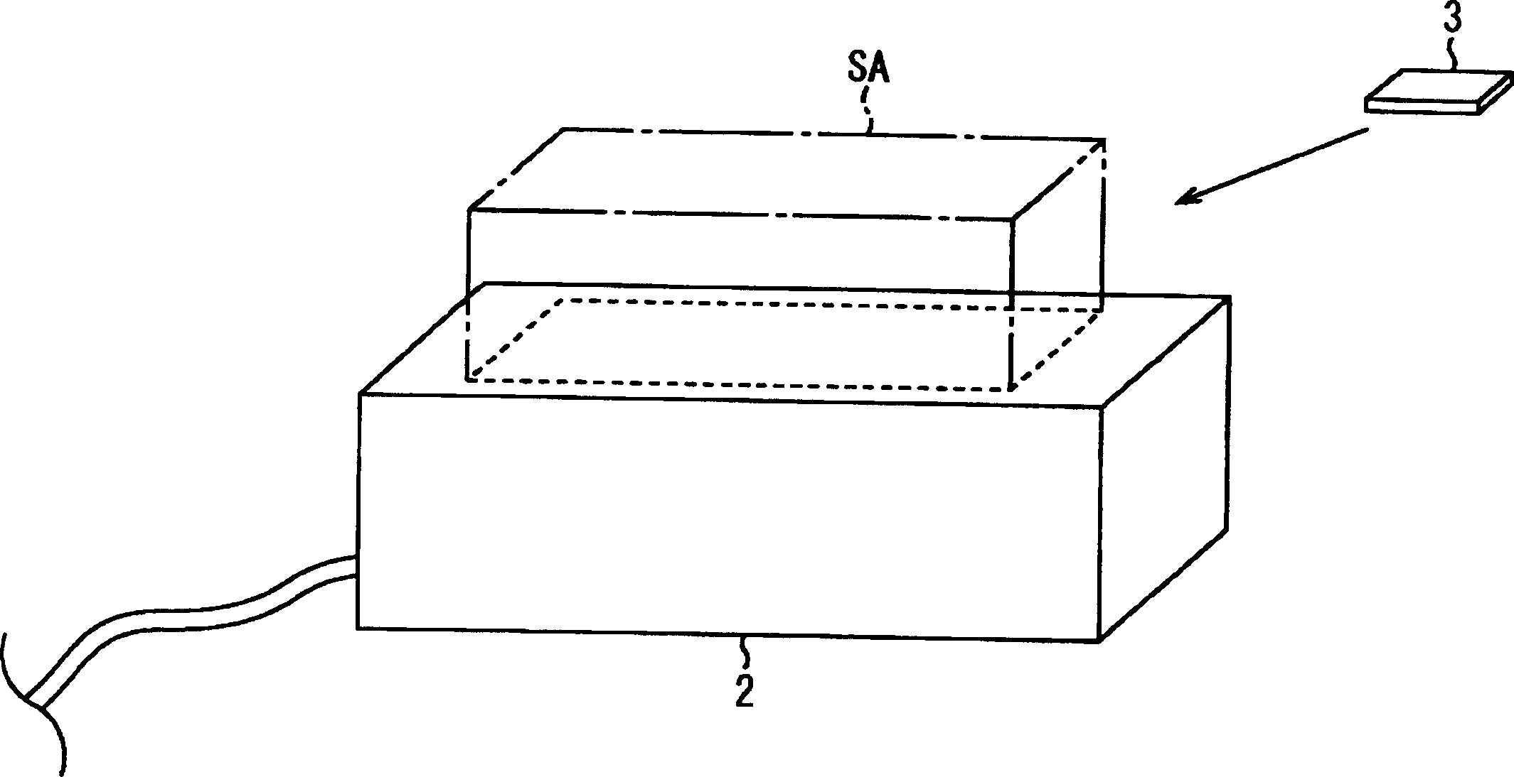
[0032] figure 1 The situation when using the loop antenna arrangement in this embodiment and allowing the data carrier 3 to approach the service area SA of the reader / writer 2 is shown.

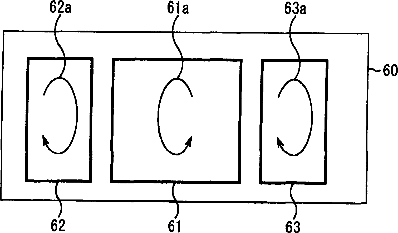
[0033] Such as figure 2 As shown, the loop antenna device according to this embodiment has three small loop coils for data transmission, that is, a first small loop coil 61, a second small loop coil 62, and a third small loop coil 63 formed on a base 60. . The loop antenna arrangement according to the invention can have a greater number of small loop coils.

[0034] The area of ​​the first small loop coil 61 is twice that of the second small loop coil 62 or the third small loop coil 63 . further, such as figure 2 As shown, the direction of the alternating magnetic field 61a generated in the first small toroidal coil 61 is opposite to the d...


PUM


Abstract

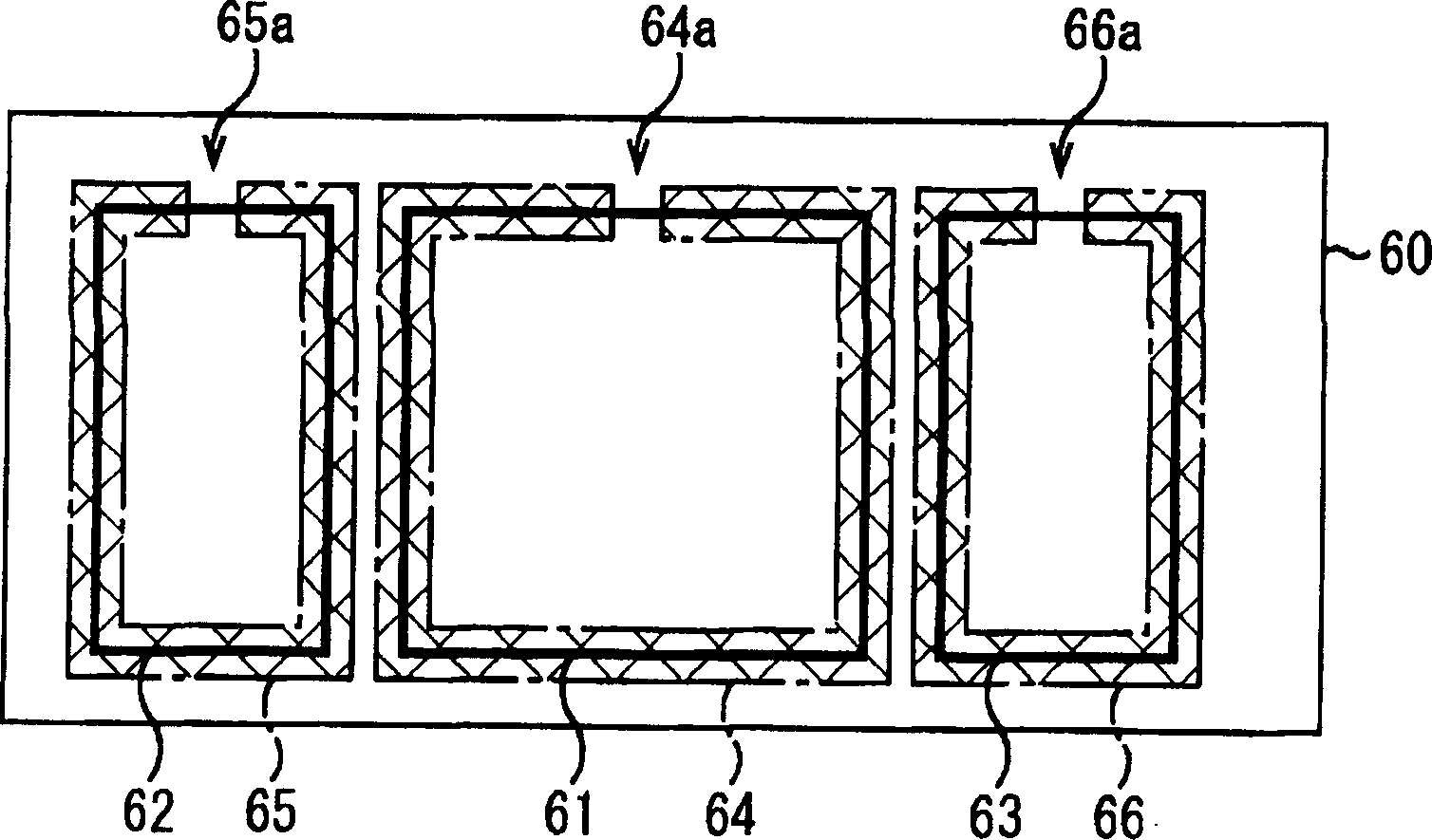
A plurality of small loop antenna cells 61, 62 and 63 are magnetically coupled to an antenna coil 8 of a non-contact type data carrier 3. In the plurality of small loop antenna cells, the directions of the magnetic moments of the signals transmitted to the non-contact type data carrier 3 are opposite to each other, the sum of the magnetic moments generated from all the small loop antenna cells 61 to 63 is zero and a conductor forming a short ring pattern 67 is provided collectively for the plurality of small loop antenna cells. Thus, imbalance caused between the small loop antenna cells 61 to 63 can be compensated for by the short ring pattern 67.

Description

technical field [0001] The present invention relates to a loop antenna device, in particular to a loop antenna device more suitable for a reader / writer device of an electromagnetic induction type non-contact data carrier system, wherein data transmission and reception are performed on a plurality of data carriers It is performed in a non-contact state with the loop antenna unit. Background technique [0002] In general, a data carrier system comprises a reader / writer device and a data carrier. The antenna arrangement of the reader / writer device supplies a modulated alternating magnetic field to the service area for transmitting data or commands to the data carrier. [0003] The data carrier utilizes combined coils to receive a modulated alternating magnetic field supplied to the service area to generate an electromotive force, which is rectified and used as an operating power source for the data carrier. The data carrier also performs prescribed operations, such as demodul...

Claims


Application Information

Patent Timeline
Patent Type & Authority Applications(China)
IPC IPC(8): G06K7/08H01Q7/04
CPCG08B13/2474G06K7/10336H01Q7/04
Inventor 深野孝和小杉康彦朝内升石井英一
Owner SEIKO EPSON CORP
Learn More