
Electro-mechanic mixed driving system of automobile

A hybrid drive and electromechanical technology, applied in the direction of power devices, vehicle components, pneumatic power devices, etc., can solve the problems of increased cost, high cost of the second inverter, high cost of the inverter, etc.

Inactive Publication Date: 2005-03-16
段志辉
View PDF1 Cites 4 Cited by
  • Summary
  • Abstract
  • Description
  • Claims
  • Application Information

AI Technical Summary

Problems solved by technology

However, this system does not take into account the high cost of the inverter. Not only is the cost of the inverter high, but its cost also increases with the increase of its power.
The system not only uses two inverters, but also the power of the second inverter is particularly large (this is because the drive motor relies on a single second inverter to provide it with AC power, and the drive motor is used to meet the needs of the vehicle. When accelerating at low and medium speeds, a relatively large driving torque must be selected), so the cost of the second inverter B is higher
In addition, this system also has a shortcoming that when the vehicle is accelerating at low or medium speeds, the alternating current generated by the starter motor must be converted several times by the first inverter A, the battery, and the second inverter B before it can be sent to the inverter. Drive the motor, which will undoubtedly cause energy loss and reduce the energy utilization rate of the engine

Method used


Image

  • Electro-mechanic mixed driving system of automobile
  • Electro-mechanic mixed driving system of automobile
  • Electro-mechanic mixed driving system of automobile

Examples


Embodiment 1

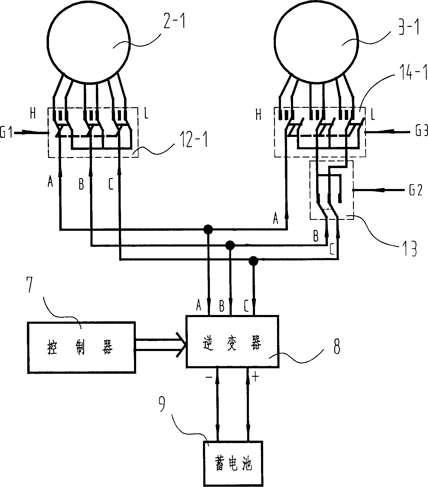
[0043] see figure 1 , which is an example where both the starter motor and the drive motor are multi-speed multi-phase AC motors. The system includes an engine 1, a starter motor 2, and a drive motor 3, the output shaft 11 of the engine is connected with the rotor shaft of the starter motor 2, the rotor shaft 4 of the drive motor is connected with the input shaft of the differential 5, and the differential 5 Link with the axle of a pair of front wheels or a pair of rear wheels 6 respectively. The system also includes a controller 7, inverter 8 and storage battery 9, the signal input end of the controller 7 is provided with the signal input interface of the engine speed sensor 15, the driving motor speed sensor 16 and the driving signal sensor 17, wherein the driving The signal sensor 17 should include an acceleration (accelerator pedal) sensor 17-1, a deceleration (brake pedal) sensor 17-2, a start (start lock) sensor 17-3 and an advance / retreat (advance and retreat joystick)...

Embodiment 2

[0054] see you again figure 1 , in order to improve the transmission efficiency of the system of the first embodiment, a clutch 10 can be added between the rotor shaft of the starter motor 2 and the rotor shaft of the drive motor 3 , and the clutch 10 is controlled by the controller 7 on and off. This clutch is only used on the high-speed gear (third gear), and its control process is: when the vehicle accelerates on the third gear, the controller 7 detects that the driving motor and the engine speed are consistent (that is, the input shaft of the clutch is the same as the output shaft speed). , are all 3000 rpm), that is, the control clutch 10 is closed, so that the engine and the driving motor can jointly drive the vehicle. At this time, the power of the engine is directly transmitted to the wheels, which can improve the transmission efficiency of the system; when the vehicle enters When driving at a constant speed, the engine drives the vehicle independently, while the start...

Embodiment 3

[0056] see Figure 6 In order to increase the flexibility of the system transmission ratio design in the above-mentioned embodiment 2 system, a single-stage gear transmission 18 can be added at the joint between the output shaft of the clutch 10 and the rotating shaft of the drive motor 3 . For example: for a system using a 2+1 two-speed drive motor, when the single-stage gear transmission 18 is not added, the transmission ratio of the third gear is 4 times that of the first gear; if the single-stage gear transmission is added 18. The three-speed system is equivalent to adding a speed gear to become a four-speed system, and if the transmission ratio R of the transmission is set to 10 9, the transmission ratio of the fourth gear is the first gear transmission ratio 4R (4.44) times, where R = 10 / 9 = 1.111. It can be seen that by correspondingly changing the speed ratio of the single-stage gear transmission 18, the speed ratio of the 2+1 two-speed drive motor system can be flexi...


PUM


Abstract

The invention relates to a kind of automobile electrical-mechanical mixed driving system . It includes engine , starter motor , driving motor , battery , an inverter that provides alternating current to the starter motor and the driving motor , a controlling device that can judge the needed speed gear of the car and calculate the driving torsion or speed needing amount of the car , meanwhile give the corresponding speed gear and the power supply frequency of the electrical machinery or controlling signal of phase place , according to the rotational speed signal of the engine and the driving motor and the driving signal . Among them , the starter motor and the driving motor can adopts multi-speed multi-phase alternating current reaction electrical machinery , or the starter motor adopts single-speed multi-phase alternating current electrical machinery and the driving motor adopts multi-speed multi-phase alternating current electrical reaction machinery , or the starter motor adopts multi-speed multi-phase alternating current electrical reaction machinery and the driving motor adopts single-speed multi-phase alternating current electrical machinery . The characteristic of the invention is that it saves the mechanical gearbox , using an inverter supply alternating current for two electrical machineries , reduce fabrication cost o the system , and improves the motor utilization ratio of energy .

Description

technical field [0001] The invention relates to an automobile driving system, in particular, it is an automobile electromechanical hybrid driving system, which can be used for large and small passenger cars, off-road vehicles and light trucks. Background technique [0002] The driving of the existing ordinary automobile is to convert the chemical energy of the fuel into mechanical energy by the engine, and then transmit it to the wheel shaft through the transmission mechanism, thereby turning the wheels to drive the vehicle. The power demand of the vehicle during driving is very uneven. For example, when accelerating and climbing a slope, the power demand is large, but when driving at a constant speed on flat ground, the power demand is small. Generally speaking, the high power demand lasts The time is short, and the low power lasts a long time. In order to meet the vehicle's demand for high power when accelerating and climbing, ordinary cars must be equipped with high-powe...

Claims


Application Information

Patent Timeline
Patent Type & Authority Applications(China)
IPC IPC(8): B60K6/22
Inventor 段志辉章玲玲
Owner 段志辉
Learn More