
A shunt regulator for solar cell array

A shunt regulator, solar cell technology, applied in the direction of conversion equipment without intermediate conversion to AC, can solve problems such as application, difficult spacecraft, etc., to improve reliability, suppress current spikes, and simplify different reference voltage generation circuits. Effect

Active Publication Date: 2013-01-23
BEIJING SATELLITE MFG FACTORY
View PDF0 Cites 15 Cited by
  • Summary
  • Abstract
  • Description
  • Claims
  • Application Information

AI Technical Summary

Problems solved by technology

Enlarging the special circuit using thick film technology can reduce the volume and weight of the unit circuit, but the backwardness of domestic thick film technology makes it difficult for this design to be practically applied in spacecraft

Method used


Image

  • A shunt regulator for solar cell array
  • A shunt regulator for solar cell array
  • A shunt regulator for solar cell array

Examples


Embodiment Construction

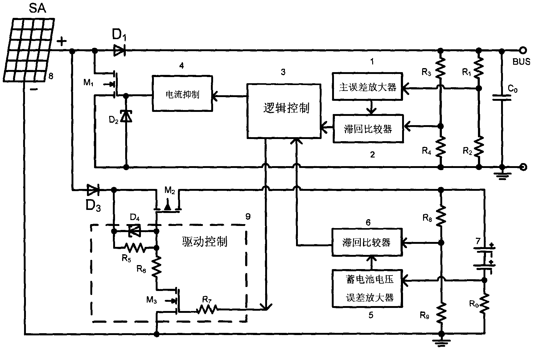
[0027] like figure 2As shown, it is a schematic diagram of a shunt regulator for a solar battery array of the present invention, which mainly includes a main error amplifier 1, a battery voltage error amplifier 5, a first hysteresis comparator 2, a second hysteresis comparator 6, and a current suppression unit 4. The shunt adjustment tube M1, the charge adjustment tube M2, the logic control unit 3 and the drive control unit 9. The main error amplifier 1 is mainly used to adjust the output bus voltage. After comparing the sampled bus voltage with the first reference voltage, its output signal is used as an input of the first hysteresis comparator 2. The first reference voltage can generally be obtained by Provided by Zener diodes, it can also be provided by other voltage reference sources. The first hysteresis comparator 2 is mainly used to generate the driving pulse of the shunt adjustment tube, and its other input comes from the step-by-step sampling of the bus voltage. Th...


PUM


Abstract

A shunt regulator for solar cell arrays, including a power MOS tube M1 for splitting solar cell arrays, a power MOS tube M2 for charging batteries with solar cell arrays, and a main error amplifier for adjusting bus voltage , the battery error amplifier used to regulate the battery charging current. The output of the main error amplifier enters the logic control after passing through the hysteresis comparator to generate shunt drive pulses to control the opening and closing of the power MOS transistor M1, so as to control the constant bus voltage. The output of the battery error amplifier enters the logic control after passing through the hysteresis comparator, generates driving pulses and passes through the drive control unit to control the opening and closing of the power MOS transistor M2, so as to control the size of the battery charging current. The invention adopts the power MOS tube M2 to replace the traditional charging regulator, which saves the volume and weight of the power controller, and is not only suitable for low-orbit spacecraft requiring frequent charging, but also for high-orbit regular charging spacecraft.

Description

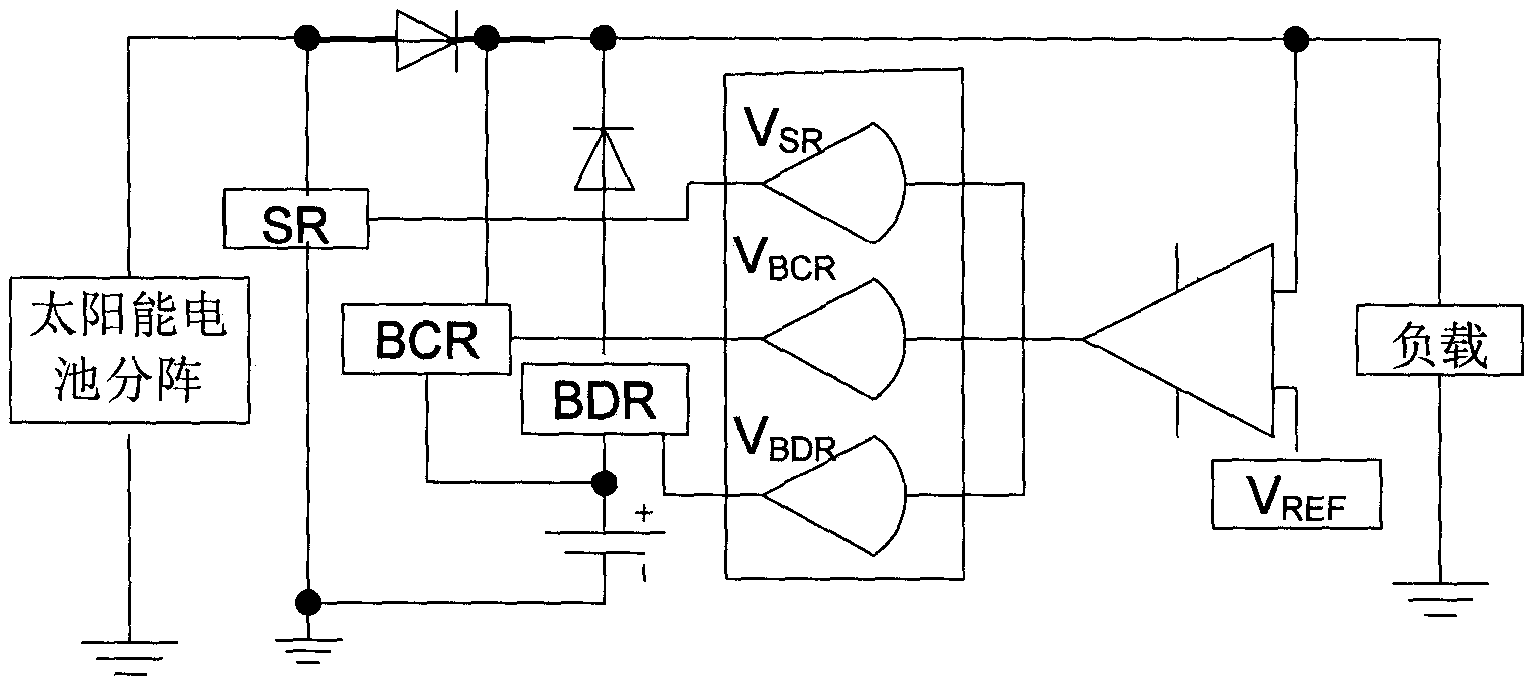
technical field [0001] The invention relates to a shunt regulator applied to solar cell arrays of spacecraft. Background technique [0002] With the rapid development of aerospace technology, the power capacity of the spacecraft power supply system continues to increase, the power of the communication series satellites increases from 2 to 3kW to 8 to 10kW, and the power of the latest generation of large-capacity communication satellites will increase to 20 to 30kW. Lifespan increased from 8 to 15 years. In addition, in order to reduce the launch cost and increase the success rate of launch, the volume and weight of the electronic equipment are required to be further reduced, thus the volume and weight of the power controller that supplies power to the electronic equipment is also required to be correspondingly reduced. [0003] The currently used fully adjustable bus power controllers generally use figure 1 The topology shown, it mainly consists of five parts, a main error...

Claims


Application Information

Patent Timeline
Patent Type & Authority Patents(China)
IPC IPC(8): H02M3/06H02M3/08
Inventor 雷卫军万成安
Owner BEIJING SATELLITE MFG FACTORY
Learn More