
Piezoelectric resonator component

A piezoelectric resonance and piezoelectric resonator technology, which is applied in the direction of electrical components, piezoelectric devices/electrostrictive devices, impedance networks, etc., can solve problems such as difficulty in stably controlling clutter, increased cost, and increased manufacturing steps

Active Publication Date: 2005-02-02
MURATA MFG CO LTD
View PDF2 Cites 4 Cited by
  • Summary
  • Abstract
  • Description
  • Claims
  • Application Information

AI Technical Summary

Problems solved by technology

This known technology also utilizes the attenuation effect of the damping material, which increases the manufacturing steps and increases the cost
[0008] Depending on the position of the damping material, the attenuation effect will also change, making it difficult to control clutter stably

Method used


Image

  • Piezoelectric resonator component
  • Piezoelectric resonator component
  • Piezoelectric resonator component

Examples


Embodiment Construction

[0031] Preferred embodiments of the present invention will be described below with reference to the accompanying drawings.

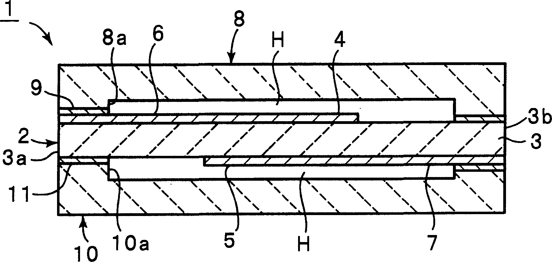
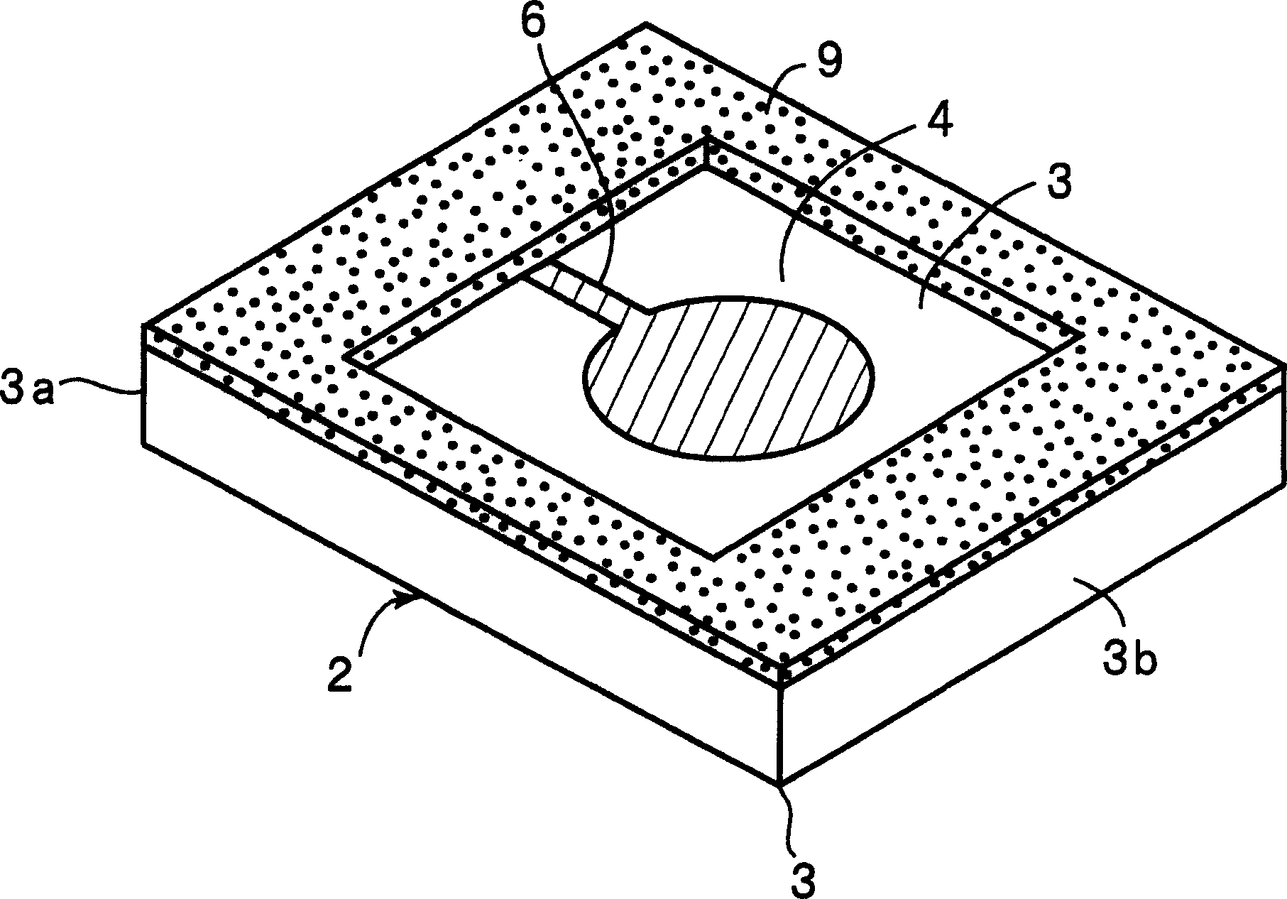
[0032] Figure 1A It is a longitudinal sectional view of the piezoelectric resonant component 1 of the first preferred embodiment of the present invention, Figure 1B is a perspective view of the main part of the piezoelectric resonance component.

[0033] The piezoelectric resonance part 1 includes an energy trap type piezoelectric resonator 2 . The piezoelectric resonator 2 includes a piezoelectric substrate 3 having a substantially rectangular planar shape. The piezoelectric substrate 3 made of piezoelectric ceramics such as lead zirconate titanate ceramics or lead titanate ceramics is polarized in its thickness direction.

[0034] A first vibrating electrode 4 having a substantially circular planar shape is provided at a position substantially centered on the top surface of the piezoelectric substrate 3 . The second vibration electrode 5 is provi...


PUM


Abstract

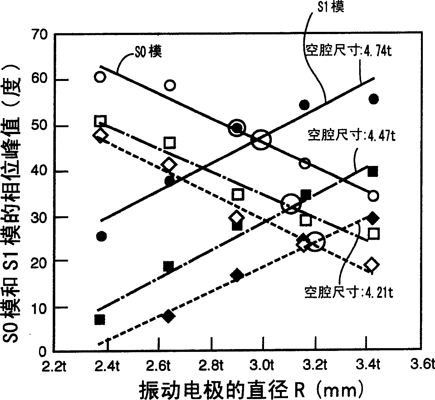
A piezoelectric resonator component includes an energy-trapped piezoelectric resonator utilizing a third order harmonic wave of thickness longitudinal vibration and including a piezoelectric substrate having first and second major surfaces and polarized in a direction of thickness between the first and second major surfaces, and first and second vibrating electrodes opposed to each other with the piezoelectric substrate interposed therebetween, and first and second casing substrates respectively laminated on the first and second major surfaces of the piezoelectric resonator so that cavities are arranged so as not to interfere with vibration of a vibration section where the first and second vibrating electrodes face each other through the piezoelectric substrate. The first and second vibrating electrodes are dimensioned so that the difference between the peak values of the phases of S0 and S1 modes of the fundamental wave of the thickness longitudinal vibration falls within a range of about + / -5 degrees.

Description

technical field [0001] The present invention relates to an energy trap type piezoelectric resonant part, in particular to an energy trap type piezoelectric resonant part capable of suppressing the fundamental wave of thickness longitudinal vibration acting as clutter. Background technique [0002] An energy trap type piezoelectric resonator is widely used as an oscillator. Choose to use multiple vibration modes according to the target frequency. [0003] Japanese Unexamined Patent Application Publication No. 8-148967 discloses an energy trap type piezoelectric resonator 101 using a fundamental wave of thickness longitudinal vibration. Such as Figure 9 As shown in the perspective view in FIG. 2 , a known energy well type piezoelectric resonator 101 includes a piezoelectric substrate 102 having a rectangular planar shape. The piezoelectric substrate 102 is made of piezoelectric ceramics polarized in the thickness direction. A vibrating electrode 103 having a circular plana...

Claims


Application Information

Patent Timeline
Patent Type & Authority Applications(China)
IPC IPC(8): H03H9/17H01L41/08H03H3/02H03H9/02H03H9/10H03H9/13H03H9/15
CPCH03H9/132H03H9/1035H03H9/0207H03H9/177H03H9/02157
Inventor 吉尾雅一小谷谦一山田光洋
Owner MURATA MFG CO LTD
Learn More