Rotor position detection of a switched reluctance drive
A rotor position and rotor technology, applied in electronic commutator, AC motor control, electrical components, etc., can solve problems such as unstable motor performance
- Summary
- Abstract
- Description
- Claims
- Application Information
AI Technical Summary
Problems solved by technology
Method used
Image
Examples
Embodiment Construction
[0034] The phase inductance period of a switched reluctance motor is the period of change of phase or inductance per phase, for example the period between the maximum values when the stator poles and the associated respective rotor poles are perfectly aligned. The illustrative embodiment described uses a 2-phase switched reluctance drive device in the electric slewing mode, but any more than one phase number can be used, and the drive device can be in either the electric slewing mode or the power generation mode.
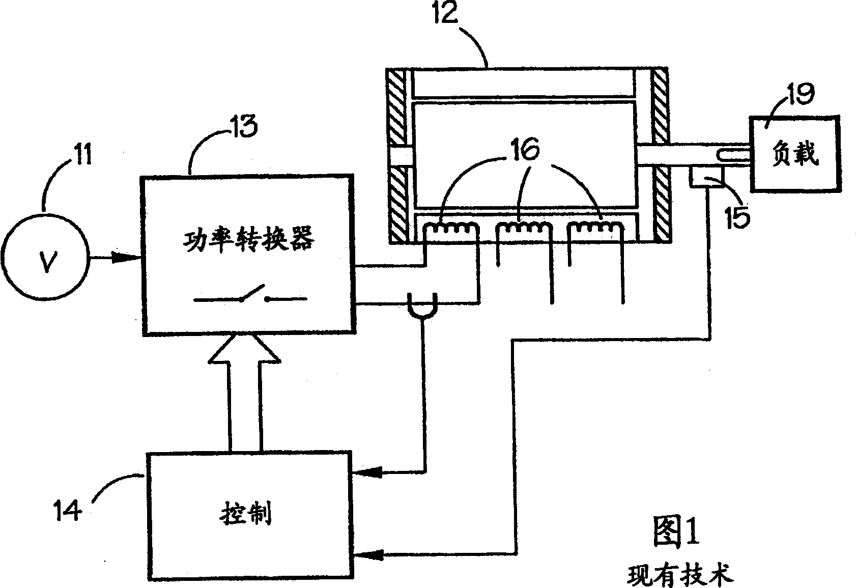
[0035] Figure 5 shows a system for implementing the method embodying the invention. Figure 6 The continuous current waveform used in the system of Figure 5 is schematically illustrated. In this system, the power converter 13 is typically the same as shown in FIG. 1, and the same reference numerals are used where appropriate. The converter 13 controls the switched reluctance motor as described above. The converter 13 itself is controlled by the controller 42. In this ...
PUM
 Abstract
Description
Claims
Application Information
 - R&D
- Intellectual Property
- Life Sciences
- Materials
- Tech Scout
- Unparalleled Data Quality
- Higher Quality Content
- 60% Fewer Hallucinations
Browse by: Latest US Patents, China's latest patents, Technical Efficacy Thesaurus, Application Domain, Technology Topic, Popular Technical Reports.
© 2025 PatSnap. All rights reserved.Legal|Privacy policy|Modern Slavery Act Transparency Statement|Sitemap|About US| Contact US: help@patsnap.com


