
Supersolution structure cntg. non-linear mask layer

A mask layer, non-linear technology, applied in the field of optical storage, achieves the effects of good readout cycle, low thickness and uniformity, and low production cost

Inactive Publication Date: 2005-01-12
SHANGHAI INST OF OPTICS & FINE MECHANICS CHINESE ACAD OF SCI
View PDF0 Cites 0 Cited by
  • Summary
  • Abstract
  • Description
  • Claims
  • Application Information

AI Technical Summary

Problems solved by technology

[0006] The problem to be solved by the present invention is to effectively improve the defects and difficulties of the above-mentioned prior art, and propose a "super-resolution structure containing a nonlinear mask layer" to solve the problem of achieving a spot size smaller than the read-out spot size in a read-only optical disc. The readout of recording points (super-resolution recording points), and the signal-to-noise ratio is very high, the readout cycle is good, and it can basically be practical

Method used


Image

  • Supersolution structure cntg. non-linear mask layer
  • Supersolution structure cntg. non-linear mask layer
  • Supersolution structure cntg. non-linear mask layer

Examples


Embodiment Construction

[0021] The present invention and its effects will be further described below in conjunction with examples.

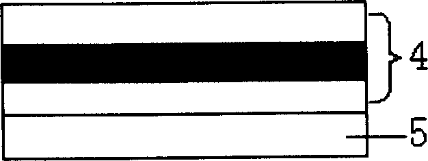
[0022] The present invention contains the super-resolution structure of the nonlinear mask layer such as figure 1 As shown, it includes a protection layer 1 , a nonlinear mask layer 2 and a protection layer 3 . The protective layer 1 and the protective layer 3 are used to prevent the non-linear mask layer 2 from being damaged or oxidized by reading heat, and the non-linear mask layer 2 is used for reading out information recording points smaller than the diffraction limit.

[0023] Protective layer 1 and protective layer 3 in the mask of the present invention are all made up of zinc sulfide with a thickness of 30nm: the composite material of silicon dioxide=80:20; (Ag 11 In 12 Sb 51 Te 26 ) Composite film composition. The protection layer 1, the nonlinear mask layer 2 and the protection layer 3 jointly form a super-resolution structure 4, see figure 2 .

[0024...


PUM

PropertyMeasurementUnit
Thicknessaaaaaaaaaa
Thicknessaaaaaaaaaa

Abstract

The disclosed structure suitable to CD ROM is composed of protection layer, non-linear reflective coating and protection layer. Characters are that the protection layer is made from composite material with proportioning as zinc sulfate : silicon dioxide = 80:20. Non-linear reflective coating layer is made from composite material with proportioning as argentine, indium, stibium and tellurium (Ag11In12Sb51Te26). Features are super resolution and high S / N larger than 40dB.

Description

Technical field: [0001] The invention belongs to the technical field of optical storage, and relates to a super-resolution structure with a nonlinear mask layer. Background technique: [0002] The rapid development of information technology requires that the devices used for information storage must have ultra-high storage density and ultra-fast access rate, which requires that the size of the recording spot of the optical disc used for information storage is getting smaller and smaller. However, as the size of the recording point decreases, the spot size required for reading the recording point also decreases accordingly. It is difficult to read such a small recording point with the existing optical system, because the size of the recording point is smaller than the readout The resolution of the spot, the signal of multiple recording points will appear in the spot, which requires the use of short-wavelength laser and high numerical aperture optical head, but due to the diff...

Claims


Application Information

Patent Timeline
IPC IPC(8): G11B7/2433
Inventor 张锋施宏仁徐文东王阳杨金涛高秀敏周飞干福熹
Owner SHANGHAI INST OF OPTICS & FINE MECHANICS CHINESE ACAD OF SCI
Learn More