Inerting protection method and protection device in use for silo of storing raw coal

A protection device, raw coal technology, applied in fire rescue and other directions, can solve problems such as inability to monitor in time, unrealistic fire fighting, difficult control, etc., and achieve the effects of direct inerting protection, flexible protection methods, and optimal protection effects.

Inactive Publication Date: 2005-01-12
BEIJING PULANDE ELECTRIC POWER TECH CO LTD
View PDF0 Cites 18 Cited by
  • Summary
  • Abstract
  • Description
  • Claims
  • Application Information

AI Technical Summary

Problems solved by technology

Because the volume of the silo is too large, when the raw coal spontaneously ignites locally, the range is small, the heat is low, and the environment is greatly disturbed. The installed combustible gas concentration, oxygen content, temperature and other sensor detection facilities cannot accurately monitor the real situation in the silo, and cannot monitor the real situation of smoldering and spontaneous combustion in the silo and in the coal seam in time, until the scope of spontaneous combustion expands When the heat is high and the concentration of combustible gas increases and then reacts, the treatment time has been delayed and it is difficult to control
[0005] For safety accidents such as smoldering, spontaneous combustion, and explosions that occur in the silo, the existing measures are limited to spraying water into the silo and unloading all the coal. It is also not feasible fo...

Method used


Image

  • Inerting protection method and protection device in use for silo of storing raw coal
  • Inerting protection method and protection device in use for silo of storing raw coal
  • Inerting protection method and protection device in use for silo of storing raw coal

Examples


Embodiment 1

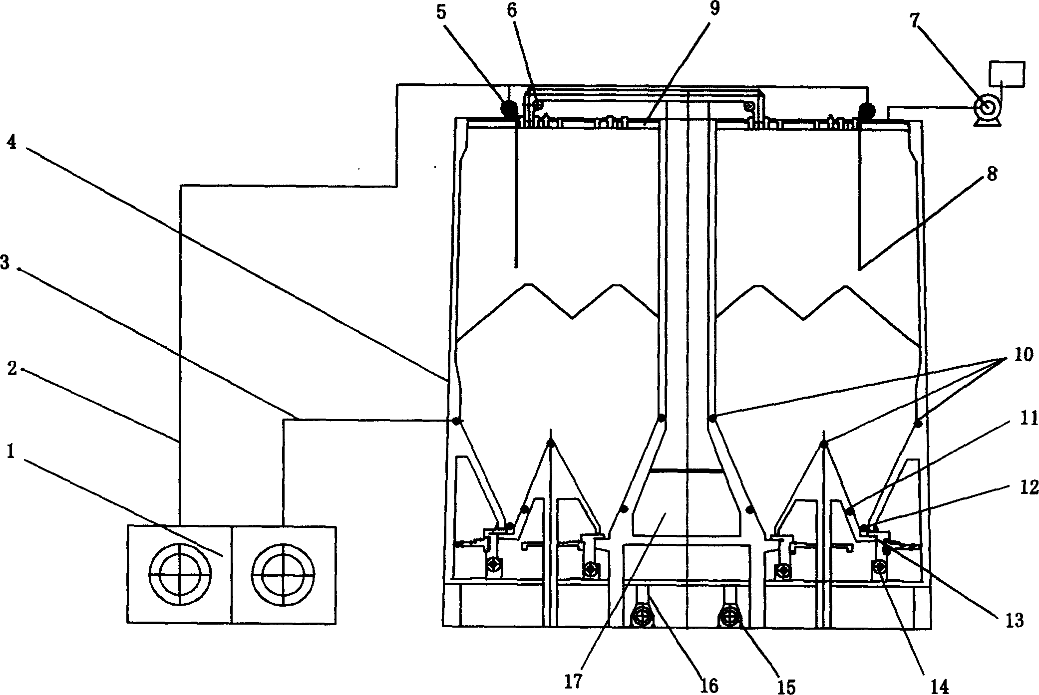
[0041] This embodiment is a specific application example of the raw coal silo inerting protection device on a large raw coal silo above 30,000 tons.

[0042] The structure of a large raw coal silo above 30,000 tons is as follows: figure 1 As shown, its main structure is a circular silo made of reinforced concrete, a hollow support column 17 is arranged in the center of the silo, and the interior of the silo is a ring structure. The upper part of the silo is a flat-top silo roof 9, on which there is a ring-type coal distributor 6 to add coal to the silo, and a dust collector 7 is used to remove the dust raised on the surface of the coal seam when adding coal. The lower part of the silo is closed in a conical shape, and a ring-shaped umbrella-shaped cone bottom is set at the bottom. Two ring-type coal unloaders 13 and ring-type coal conveyors 14 are set at the bottom of the inner and outer cones of the ring for unloading coal from the silo. Coal, the unloaded pulverized coal fa...

Embodiment 2

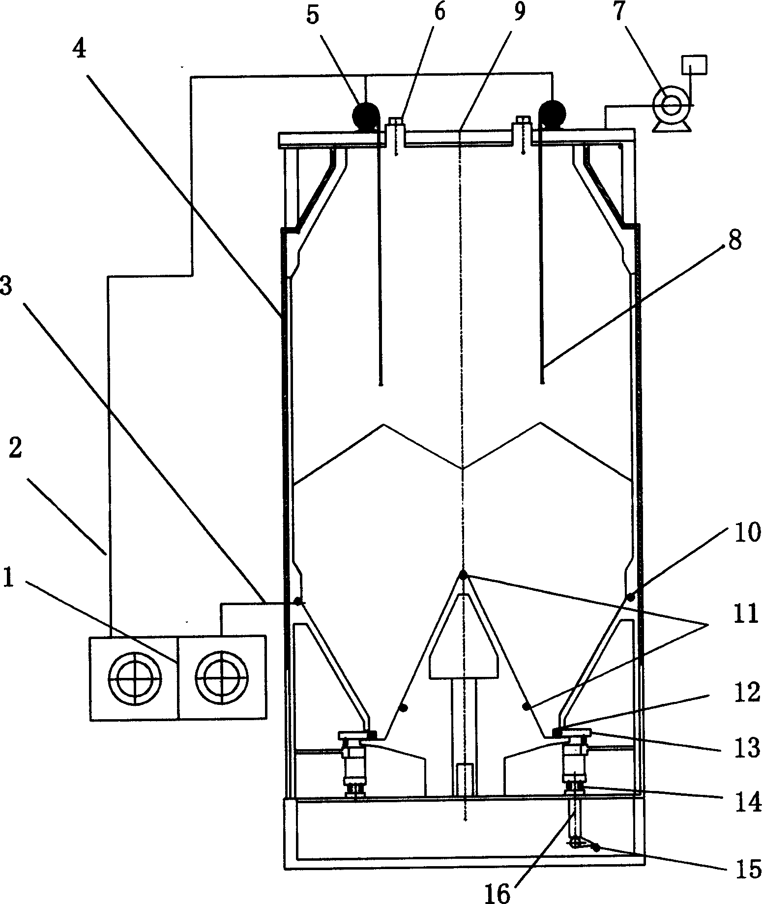
[0062] This embodiment is a specific application example of the raw coal silo inerting protection device on a medium-sized raw coal silo below 10,000 tons.

[0063] The structure of medium-sized raw coal silos below 10,000 tons is as follows: figure 2 As shown, its main structure is a circular silo made of reinforced concrete; the upper part of the silo is a flat top silo roof 9, on which a ring-type coal distribution machine 6 is provided to add coal to the silo, and a dust collector 7 is used to The dust raised on the surface of the coal seam is removed when coal is added; the lower part of the silo is conical closed, and an umbrella-shaped conical bottom is set at the bottom, and a ring-type coal unloader 13 and a ring-type coal conveyor 14 are set at the bottom of the cone for Coal is unloaded in the silo, and the unloaded coal powder falls in the coal drop pipe 16 below, and is carried away by the coal conveying belt 15.

[0064]Several telescopic inflation devices 5 ar...


PUM


Abstract

A method and mechanism for protecting the cylindrial coal bunker features that a telescopic aerator is arranged to its top for filling inertial gas, the aerating module is pre-embedded in its wall for filling inertial gas in coal, and the gas blocking module is arranged at its bottom for filling inertial to the position where coal is discharged.

Description

technical field [0001] The invention relates to a large silo for storing raw coal, in particular to a method for inerting safety protection of the raw coal in the silo. The invention also relates to a device for inerting safety protection of the raw coal in the silo. Background technique [0002] A silo is a large device used to store and unload bulk materials conveniently. It is also the main facility used by power plants to store raw coal in recent years. The raw coal silo is a cylindrical structure with a flat top and conical bottom built of reinforced concrete, with a volume of tens of thousands of m 3 , its internal structure is slightly different according to the capacity. The upper part of the silo is equipped with a ring-type coal distribution machine for coal distribution, and the lower part is equipped with a ring-type coal unloader for coal discharge, and a dust collector is installed to prevent dust from overflowing in the silo. It is a relatively closed contai...

Claims


Application Information

Patent Timeline
IPC IPC(8): A62C3/04
Inventor 朱耀平
Owner BEIJING PULANDE ELECTRIC POWER TECH CO LTD
Why Eureka
Try Eureka