


Quick Research
Generate reliable direction feasibility study reports for your R&D in just a few steps.

Technical Q&A
Discover and master advanced knowledge NOW. Basics, ideas, possibilities, all at once.

Find Solutions
As an expert in R&D theories, this can generate solutions to your technical problems instantly.

Evaluate Feasibility
Analyze your overall solution with one click, know your potential R&D risks in advance.

Monitor Landscape
Get weekly tech updates, stay abreast of the latest tech innovations and key insights.
Module for judging D.C. voltage switching quantitative input state
A technology of DC voltage switch and input status, which is applied in the field of DC voltage switch input status judgment module to achieve the effect of satisfying power consumption, low power consumption and ensuring accuracy
- Summary
- Abstract
- Description
- Claims
- Application Information
AI Technical Summary
Problems solved by technology
Method used
Image

Examples
Embodiment 1
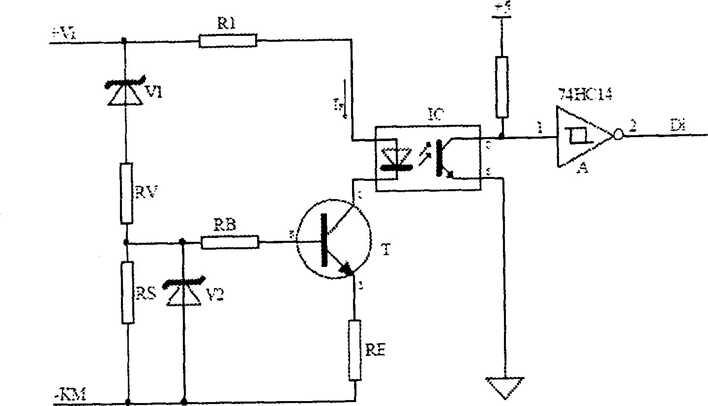
[0021] The DC voltage switch input state judging module of this embodiment is as follows: figure 2 As shown, it is mainly based on the constant current source technology in analog electronics, and is composed of an optocoupler IC, a pre-transistor T, a voltage regulator tube, and a resistor. The front end of the optocoupler IC inputs a DC voltage signal through the first resistor R1, the negative pole of the front end is connected to the collector of the pre-transistor T, and the rear end of the optocoupler IC outputs a judgment result signal through the Schmitt trigger A. The emitter of the pre-transistor T is grounded through the emitter resistor RE, the base of the pre-transistor T is connected to the base resistor RB, and a voltage regulator tube V1 and a series connection are connected between the DC voltage signal input terminal and the base resistor RB. Divider resistor RV. The connection between the base resistor RB and the voltage dividing resistor RV is grounded th...
Embodiment 2
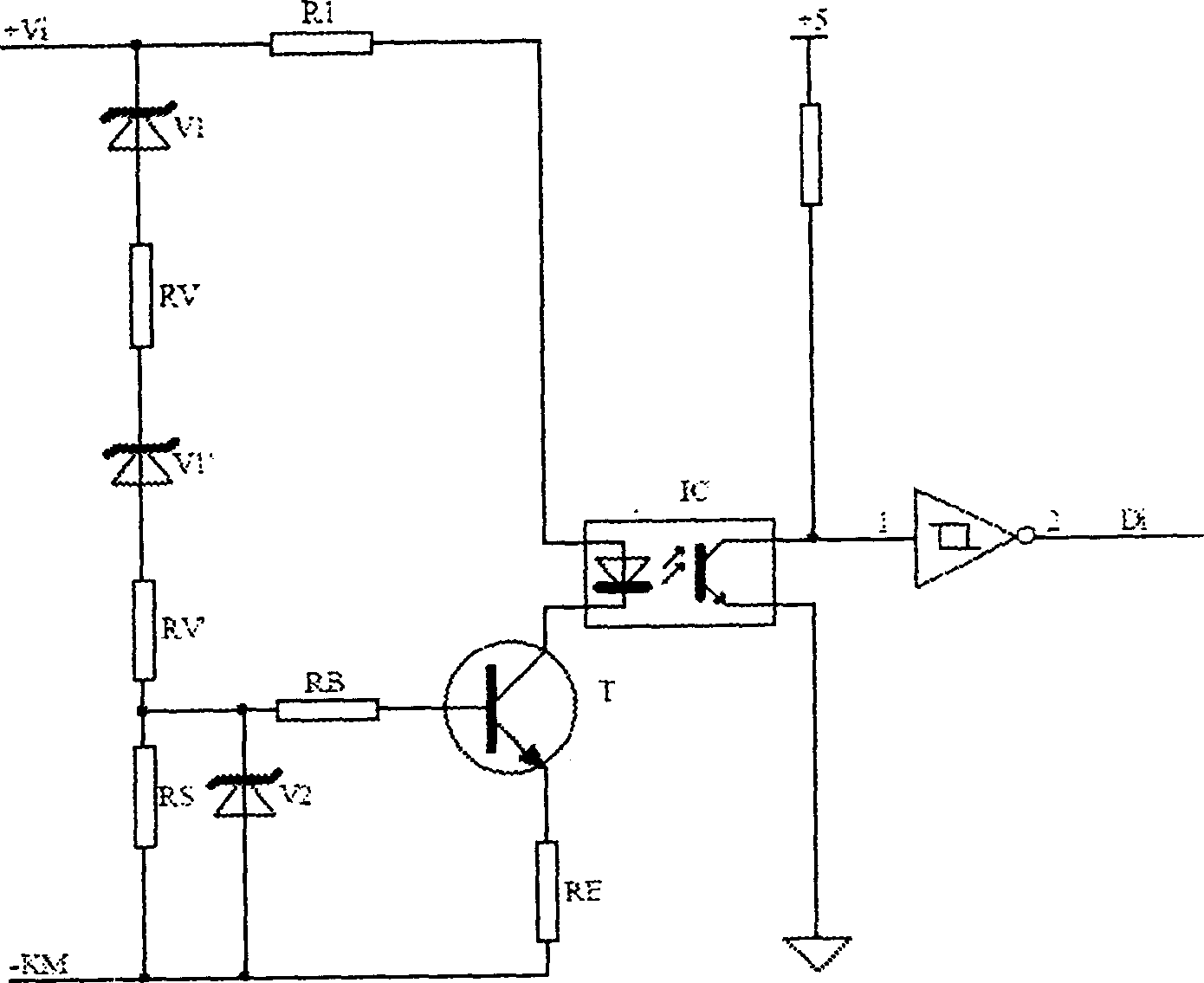
[0035] The above exemplifies the working circuit of the DC digital input judging module when the digital input voltage level is 110V. In order to make it conveniently applicable to the environment where the digital input voltage level is 220V, this embodiment is for example image 3 As shown, the series voltage regulator tube V1' and resistor RV' with the same parameters as the original voltage regulator tube V1 and resistor RV' are added. In this way, the purpose is achieved, and the cost and complexity of production are also saved.
Embodiment 3
[0037] This embodiment is a technical solution further refined and perfected on the basis of the above embodiments, such as Figure 4 As shown, its specific improvements are:
[0038] A protective diode D is added to the DC voltage signal input to avoid accidental reverse voltage from destroying the working circuit. A subsequent current-limiting resistor R is connected in series behind the protection diode D so that the current flowing through the working circuit will not be too large.
[0039] A high-voltage capacitor CH is connected in parallel after the protection diode D at the input terminal of the DC voltage signal and the subsequent current-limiting resistor R to absorb the AC component generated by the instantaneous large voltage disturbance of the switching input voltage.
[0040] Next to the high-voltage capacitor CH, a fast transient diode DQ with high withstand voltage level is connected in parallel to absorb the sudden increase of transient large current caused b...
PUM
 Abstract
Description
Claims
Application Information
 - R&D Engineer
- R&D Manager
- IP Professional
- Industry Leading Data Capabilities
- Powerful AI technology
- Patent DNA Extraction
Browse by: Latest US Patents, China's latest patents, Technical Efficacy Thesaurus, Application Domain, Technology Topic, Popular Technical Reports.
© 2024 PatSnap. All rights reserved.Legal|Privacy policy|Modern Slavery Act Transparency Statement|Sitemap|About US| Contact US: help@patsnap.com