
Waveguide antennas

A technology of waveguide antenna and waveguide, which is applied in the direction of antenna, waveguide, antenna array, etc., can solve the problems of loop gain reduction, gain increase, increase of antenna complexity and loss, etc.

Inactive Publication Date: 2004-12-15
ARGUS TECH (AUSTRALIA) PTY LTD
View PDF0 Cites 3 Cited by
  • Summary
  • Abstract
  • Description
  • Claims
  • Application Information

AI Technical Summary

Problems solved by technology

This in turn disadvantageously increases the complexity and loss within these antennas
Also, as the slots of these antennas get larger, the gain increases
However, losses increase with larger antennas, causing loop gain to decrease with length

Method used


Image

  • Waveguide antennas
  • Waveguide antennas
  • Waveguide antennas

Examples


Embodiment Construction

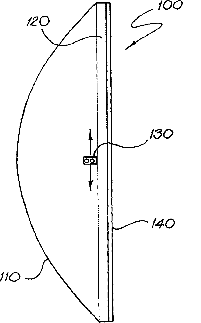
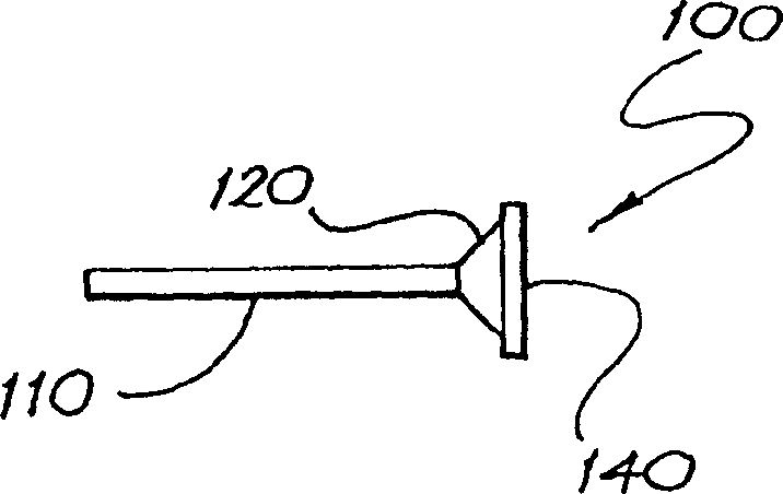
[0020] A number of waveguide antenna structures are described below. These antennas implement high gain and low loss waveguide antennas. The general characteristics of these antenna structures are as follows:

[0021] • A parallel-plate waveguide region for forming beams with desired characteristics, comprising a pair of conducting plates using shaped reflective walls to support TEM modes. The parallel plates are spaced less than half a wavelength apart so that the only waveguide mode that can propagate is one in which the electric field is uniform between the two plates.

[0022] - Illuminating the reflector from the focal area using a feed that typically includes a probe or slit. Feeds typically launch signals into reflective walls. If a narrow beam is required, the optimal reflector shape is approximately parabolic.

[0023] • Cellular base station antennas typically require a narrow beam in the elevation plane and a wide beam in the azimuth plane. Therefore, the plate...


PUM


Abstract

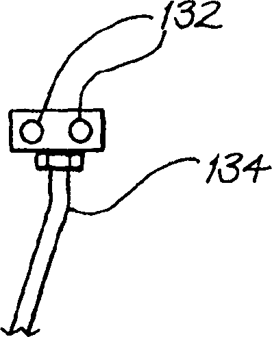
A waveguide antenna (100) for use with a cellular-communications base station includes a pair of parallel plate waveguides (110), a vertical horn (120) coupled to said waveguide (110), a feed (130) having at least one probe (132), and a polarizer (140) for rotating the plane of polarization of a radiation beam. A wall of the waveguide (110) forms the curved backwall reflector, which may have a parabolic or semi-parabolic shape. The probe (312) is located within the parallel plate waveguides (110) and the vertical horn (120). The feed (130) may have two probes (132) and be moveably connected to the waveguides (110) for adjusting the tilt of the radiation beam.

Description

technical field [0001] The present invention relates generally to antennas, and more particularly to base station antennas for cellular communication systems. Background technique [0002] Cellular base station antennas are typically implemented as phased array antennas using stripline or microstrip circuit technology or cable conductors to feed radiating elements such as dipoles or patches. The advantage of this technique is that the higher the frequency used, the greater the loss. [0003] If it is desired to tilt the beam electrically, a phase shifter is required. This in turn disadvantageously increases complexity and losses within these antennas. Also, as the slots of these antennas get larger, the gain increases. However, losses increase with larger antennas, causing loop gain to decrease with increasing length. [0004] Thus, there is a clear need for an improved antenna for use in a base station within a cellular communication system. Contents of the invention ...

Claims


Application Information

Patent Timeline
Patent Type & Authority Applications(China)
IPC IPC(8): H01Q13/06H01Q19/13H01Q21/00
CPCH01Q19/13H01Q21/0031H01Q13/06
Inventor 贝文·B·琼斯
Owner ARGUS TECH (AUSTRALIA) PTY LTD
Learn More