Tire pressure monitoring system

A tire and air pressure technology, applied in tire measurement, tire parts, vehicle parts, etc., can solve the problem of not identifying tires, and achieve a wide range of effects by reducing liability and accident chances

Inactive Publication Date: 2004-12-08
斯特姆科有限公司
View PDF4 Cites 20 Cited by
  • Summary
  • Abstract
  • Description
  • Claims
  • Application Information

AI Technical Summary

Problems solved by technology

Traditional pressure monitors only show that a low pressure reading has been encountered, but do not identify the location of the tire experiencing the low pressure

Method used


Image

  • Tire pressure monitoring system
  • Tire pressure monitoring system

Examples


Embodiment Construction

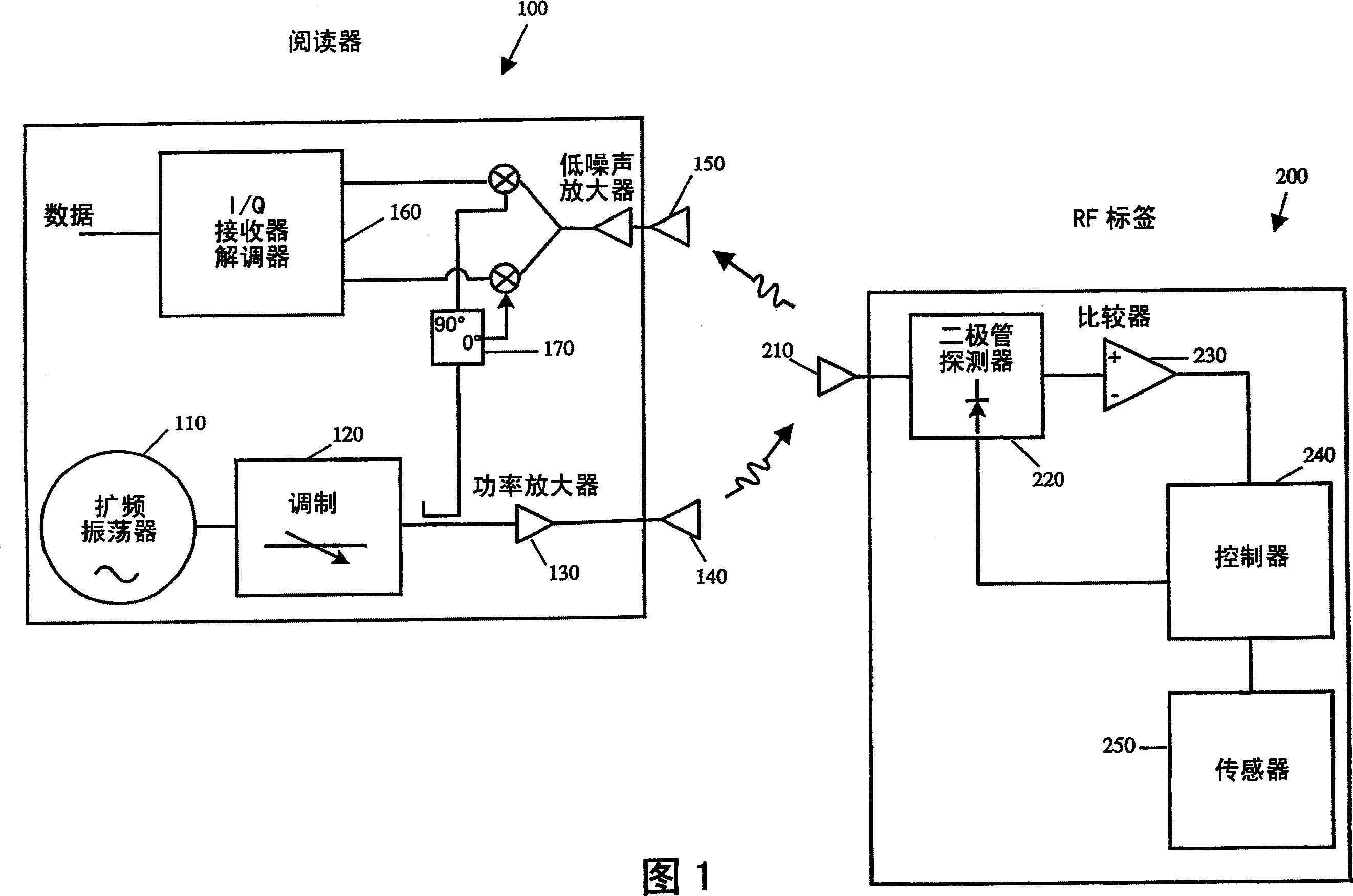
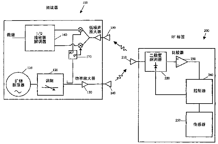
[0015] The present invention relates to a tire pressure monitoring system that utilizes radio frequency identification (RFID) technology to transmit tire pressure information to a remote receiver. The system does not require a dedicated power source at the sensing / transmitting location for data transfer purposes, and is able to locate the sensor and receive pressure readings.

[0016] The use of passive or semi-passive RF identification systems to read from an electrical "tag" is well known in the art and has been used in applications such as inventory monitoring systems, as described in U.S. Patent No. 5,850,187 and US Patent No. 6,078,251 to Landt et al., both of which are incorporated herein by reference.

[0017] Typically, such a system includes a reader, also known as a radar or transceiver, to generate a modulated or unmodulated radio frequency interrogation signal, detect a return signal from the electronic tag, and a A signal handler that handles the returned signal....


PUM


Abstract

This invention relates to systems and methods for monitoring tire pressure using radio frequency identification (RFID). The RFID systems of the present invention include a reader and a RF tag in communication with a pressure sensor. The reader of the present invention comprises an oscillator, modulator, transmitting antenna, receiving antenna and demodulator. The RF tag comprises an antenna, diode detector, comparator, controller and pressure sensor interface. The RF tag further comprises a battery which powers the electronic components of the tag. In embodiments of the present invention, the oscillator generates a signal that is fed to the modulator for encoding information. The modulated signal is then broadcast via the antenna to the RF tag. An antenna on the RF tag received the signal where the comparator and controller interpret the information sent by the reader, receive a pressure reading from the pressure sensor and transmit an encoded signal back to the reader via modulation of reflected energy. The reader in turn receives this reflected energy and demodulates the signal to retrieve the encoded information including the pressure reading.

Description

technical field [0001] The present invention relates to vehicle tire pressure monitoring systems, and more particularly to a monitoring system that utilizes backscattered radio frequency identification (RFID) to transmit tire pressure information from a radio frequency (RF) tag on the tire to a remote reader. Background technique [0002] Many monitoring devices are known for use with pneumatic vehicle tires, which measure the pressure in the tire and transmit the data to a remotely located receiver and operator interface. For example, U.S. Patent No. 3,713,092 to Ivenbaum, incorporated herein by reference, discloses a conventional tire pressure monitoring system that includes a cylindrical probe that penetrates into the ground. (threadably) engages with a tire valve stem and transmits a radio signal responsive to tire low pressure conditions to a remotely located receiver. [0003] In this conventional monitoring system, a nearby mounted detector usually includes a pressur...

Claims


Application Information

Patent Timeline
IPC IPC(8): B60C23/04
CPCB60C23/0433B60C23/0408
Inventor 马克·J·克兰兹
Owner 斯特姆科有限公司
Why Eureka
Try Eureka