Supercharge Your Innovation With Domain-Expert AI Agents!

Method for manufacturing optical fiber preform

A manufacturing method and optical fiber base material technology, applied in manufacturing tools, glass manufacturing equipment, glass production, etc., can solve problems such as increased offset, reduce core wire eccentricity, improve scattering, and reduce manufacturing costs Effect

Inactive Publication Date: 2004-11-10
MITSUBISHI CABLE IND LTD
View PDF3 Cites 1 Cited by
  • Summary
  • Abstract
  • Description
  • Claims
  • Application Information

AI Technical Summary

Problems solved by technology

Once the relative position of the glass tube and the glass rod is shifted, the offset will increase as the integration of the glass tube and the glass rod proceeds.

Method used


Image

  • Method for manufacturing optical fiber preform
  • Method for manufacturing optical fiber preform

Examples


Embodiment Construction

[0039] Next, specific embodiments of the present invention will be described with reference to the drawings.

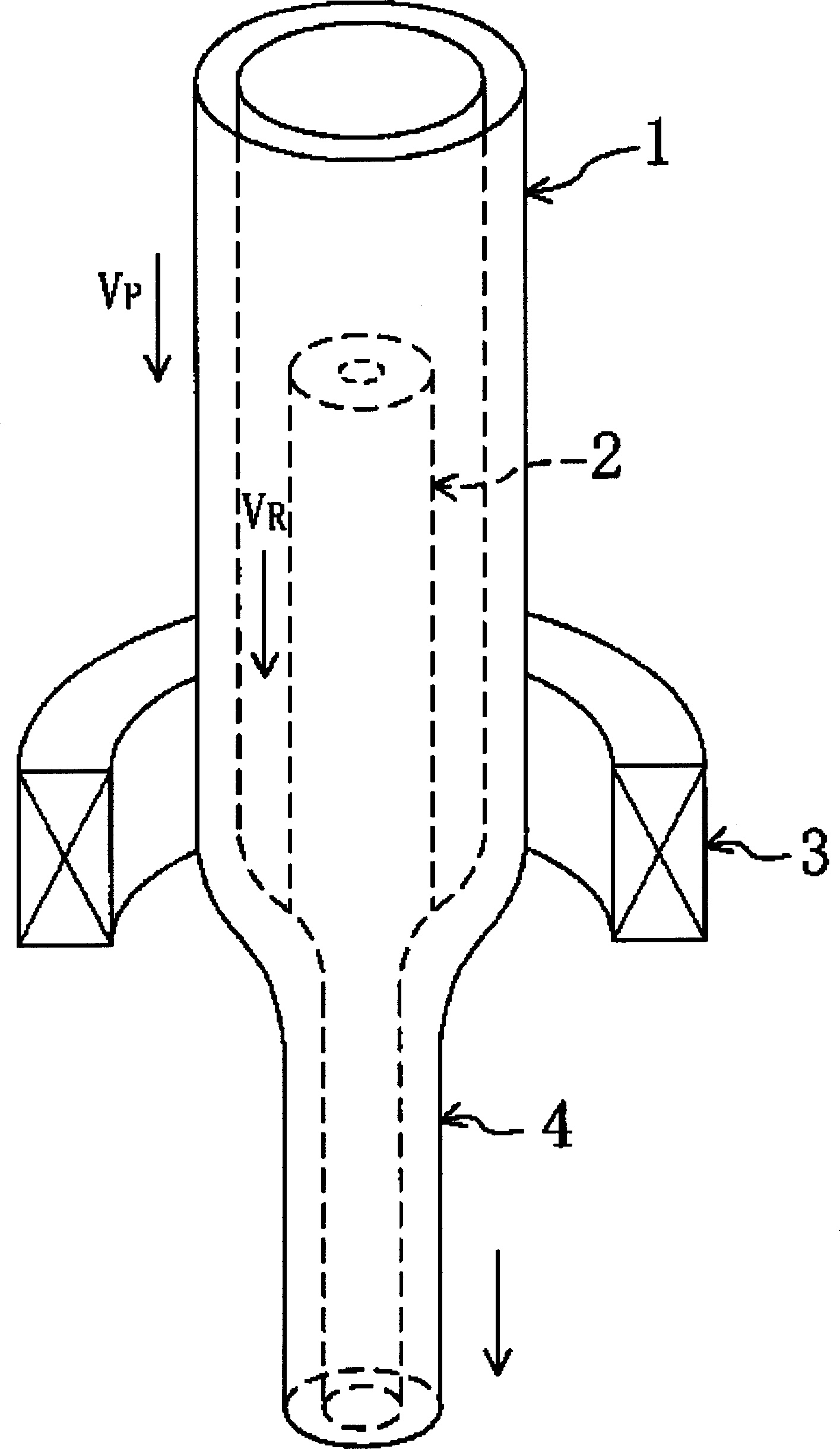
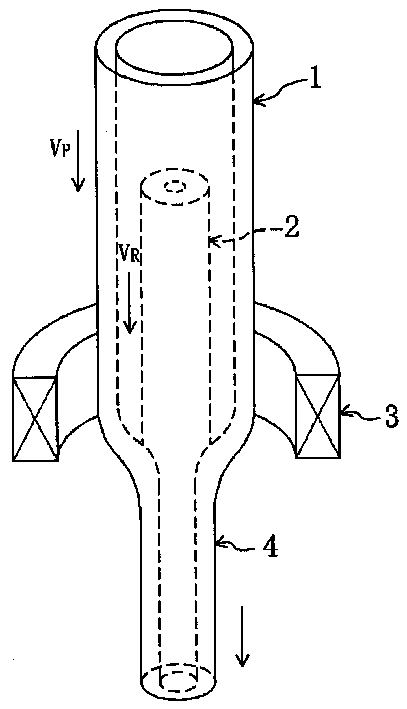
[0040] Fig. 1 shows the state during manufacture of an optical fiber preform. 1 is a glass tube for cladding, 2 is a glass rod for a core wire or a core wire and a clad, and 3 is a heater for heating both the above-mentioned glass tube 1 and glass rod 2 . As the above-mentioned glass tube 1, a glass tube produced by an OVD method or the like can be used. The above-mentioned glass rod 2 can be obtained by sintering the glass particle deposition body deposited with glass particles by the VAD method, and then stretching, or using the MVCD method to form a glass core on the inner surface of the cladding tube, and the center is solid. . Specifically, a carbon resistance heating furnace or a high-frequency induction heating furnace can be used as the heating furnace having the heater 3 described above.

[0041] In addition, the upper ends of the above-mentioned glass tub...


PUM


Abstract

An optical fiber base material 4 is produced by inserting a glass rod 2 for core or for core and clad into a glass pipe 1 for clad, decreasing the pressure in the glass pipe 1 while heating it by a heater 3, and performing simultaneous integration and stretching of the glass pipe 1 and glass rod 2. At this time, the integration of the glass pipe 1 and glass rod 2 is effected with a tension longitudinally imparted to the glass rod 2 as by setting the feed speed VR of the glass rod 2 at a value lower than the feed speed VP of the glass pipe 1.

Description

technical field [0001] The present invention relates to a manufacturing method of an optical fiber base material, which is to insert a glass rod for the core wire or a glass rod for the core wire and a glass rod for the cladding into a glass tube for cladding, heat both of them on the one hand, and face the glass tube on the other hand. The decompression treatment was performed, and the above-mentioned integration of the glass tube and the glass rod was carried out simultaneously with the stretching operation. Background technique [0002] The manufacturing methods of optical fiber base material mainly include OVD (outside vapor deposition) method, VAD (axial vapor deposition) method and MCVD (modified chemical vapor deposition) method. In the VAD method and the MCVD method, from the viewpoint of productivity, after the core wire or the glass rod for the core wire and the cladding is manufactured, other processes are used to make the cladding, which accounts for most of the ...

Claims


Application Information

Patent Timeline
Patent Type & Authority Applications(China)
IPC IPC(8): C03B37/012
CPCC03B37/0124Y02P40/57C03B37/012
Inventor 伊藤秀明金正高长江伸定福田秋彦下野智则宫下启二
Owner MITSUBISHI CABLE IND LTD
Features
  • R&D
  • Intellectual Property
  • Life Sciences
  • Materials
  • Tech Scout
  • Unparalleled Data Quality
  • Higher Quality Content
  • 60% Fewer Hallucinations
Learn More