Eddy current inspection technique

A current and eddy current technology, used in electromagnetic measurement devices, electrical/magnetic thickness measurement, measurement devices, etc., can solve the problems of local wall thickness reduction, inability to detect corrosion points, and size increase

Inactive Publication Date: 2004-11-10
SHELL INT RES MAATSCHAPPIJ BV
View PDF3 Cites 6 Cited by
  • Summary
  • Abstract
  • Description
  • Claims
  • Application Information

AI Technical Summary

Problems solved by technology

[0007] Corrosion spots whose size is comparable to the size of the excitation coil can be detected with this known device, but it has been found that this device cannot detect corrosion spots whose size is much smaller than the size of the coil, and such small corrosion spots May reduce local wall thickness to very severe levels
Also, such small corrosion spots may grow rapidly in size when, for example, liquid water is present between the pipe and the insulating material surrounding the pipe.

Method used


Image

  • Eddy current inspection technique
  • Eddy current inspection technique
  • Eddy current inspection technique

Examples


Embodiment Construction

[0025] In the following description, the same reference numerals denote the same components.

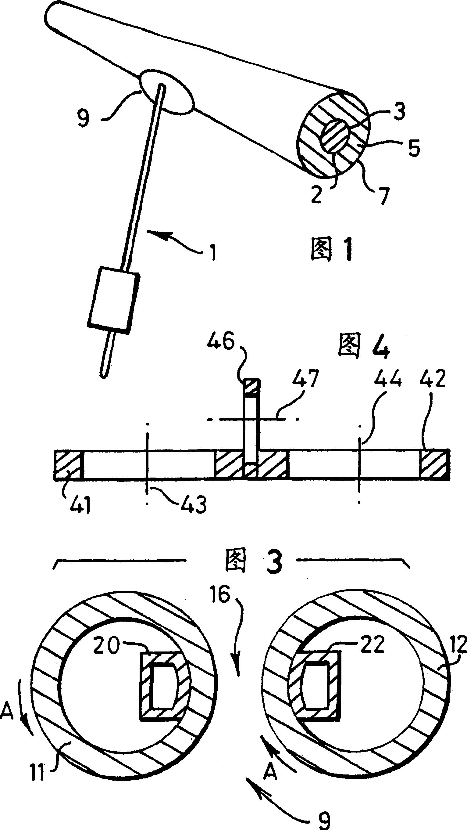
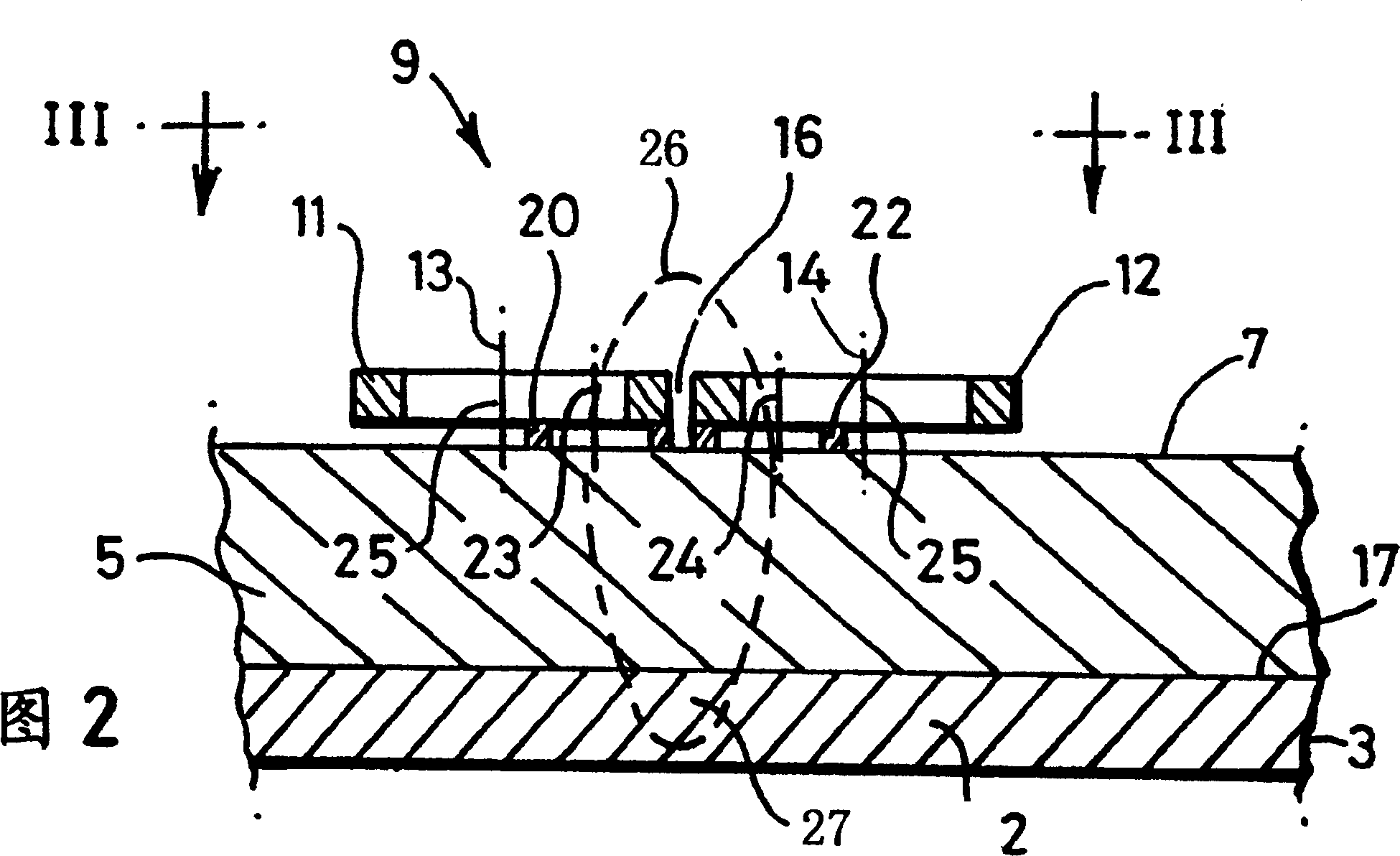
[0026] FIG. 1 shows a probe 1 for detecting objects made of conductive materials. This probe 1 can be used to detect the thickness of a pipe wall 2 on a pipe 3 to detect the corrosion state on the pipe wall 2 . Corrosion may occur at the outer or inner surface of the pipe wall 2 . A layer of insulating material layer 5 is arranged around the pipe 3, and the outside of the insulating material layer 5 is covered with a sleeve 7 made of thin metal steel. The probe 1 comprises a means 9 for carrying out the detection of an object consisting of electrically conductive material, and during normal operation the means 9 is held in position opposite the outer surface of the steel sleeve 7.

[0027] As shown in Figures 2 and 3, the device 9 for detecting objects made of conductive material includes a non-steady signal transmitter for generating a non-steady electromagnetic field in objects su...


PUM

PropertyMeasurementUnit
thicknessaaaaaaaaaa
diameteraaaaaaaaaa
thicknessaaaaaaaaaa

Abstract

Device (9) for inspecting an object (2) of electrically conductive material, comprising a non-static-signal transmitter for generating an electromagnetic field in the object (2), and a receiver (20, 21) for measuring the variations of the eddy current generated by the non-static electromagnetic field and for producing a signal representing the decay of the eddy current, wherein the non-static-signal transmitter comprises at least two laterally spaced-apart emitters (11, 12) for emitting an electromagnetic field, which emitters (11, 12) are, during normal operation, so driven that the resulting electromagnetic field in the central region (26), between the emitters (11, 12), is intensified.

Description

[0001] This application is a divisional application of the application with the application number 97196272.3, the application date is July 11, 1997, and the invention name is "eddy current detection technology". technical field [0002] The present invention relates to techniques for detecting objects made of conductive materials. The technical term "detecting an object" used in this specification and claims refers to measuring the thickness of an object, detecting whether there is a subsurface crack in an object, detecting the non-conductive Perform technical operations such as measuring the thickness of a layer of non-reactive material. Such objects may be, for example, container walls, pipe walls, and the like. Background technique [0003] The effective thickness of objects such as steel vessels, water pipes and tanks may change locally due to external or internal corrosion. For objects covered with a layer of insulating material, if the corrosion condition is to be d...

Claims


Application Information

Patent Timeline
Patent Type & Authority Applications(China)
IPC IPC(8): G01B7/00G01B7/06G01N27/90
CPCG01N27/904G01B7/06
Inventor 佩奇斯·威勒姆·万·安德尔马克·瑟道尔·鲁杰玛滕·洛伦兹里克·埃多杜·里卡多·迈耶
Owner SHELL INT RES MAATSCHAPPIJ BV
Why Eureka
Try Eureka