Film tearing method
A technology of protective film and printed circuit board, applied in electrical components, printed circuit manufacturing, printed circuit and other directions, can solve problems such as poor processing quality and accumulation
- Summary
- Abstract
- Description
- Claims
- Application Information
AI Technical Summary
Problems solved by technology
Method used
Image
Examples
no. 1 example
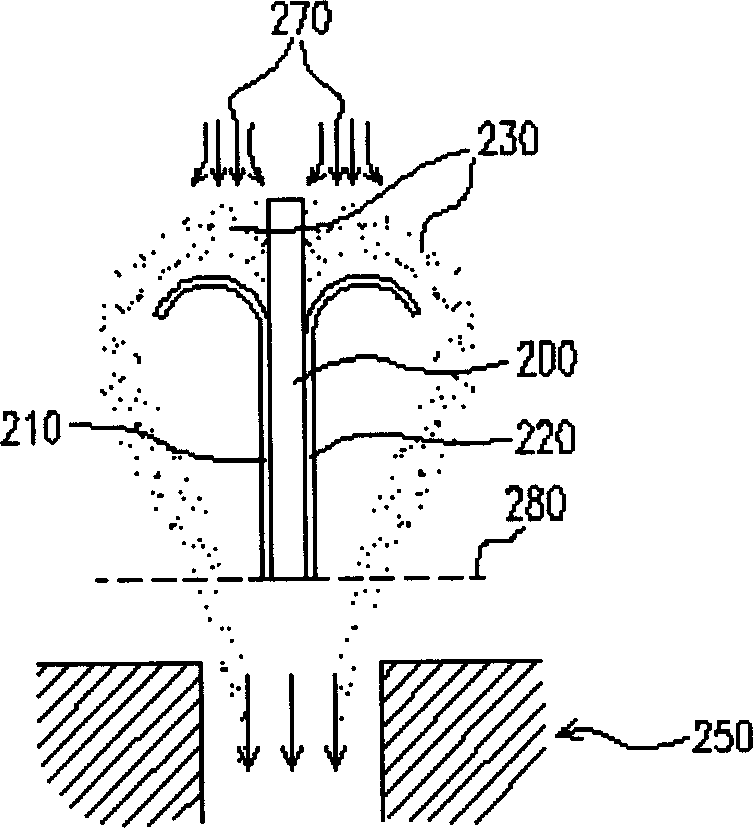
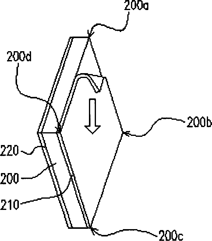
[0032] figure 2 Shown is a schematic diagram of the film tearing method using ion wind according to the first preferred embodiment of the present invention. Please refer to figure 2 As shown, according to the film tearing method of the first preferred embodiment proposed by the present invention, a first protective film 210 is torn off from the surface layer of the printed circuit board 200 through two suction cup units (not shown). Wherein, the printed circuit board 200 is placed in a substantially vertical state relative to a horizontal plane, and a first protective film 210 and a second protective film 220 are pasted on the surface layer of the printed circuit board 200 and the opposite surface layer respectively. The film tearing method according to the first preferred embodiment of the present invention includes at least the following steps: Step 1, providing a printed circuit board 200, which has a first protective film 210 and a second protective film 220 , respecti...
no. 2 example
[0040] FIG. 6 is a schematic diagram of the relationship between the printed circuit board and the horizontal plane in the film tearing method according to the second preferred embodiment of the present invention. Please refer to FIG. 6 , the steps of the film tearing method are roughly the same as the film tearing method of the first preferred embodiment, and the similarities will not be repeated here. The difference is that in step 2, an angle 290 can also be formed between the printed circuit board 200 and the horizontal plane 280, and the angle 290 is not limited to 90 degrees as in the first embodiment, and can also be between 30 degrees and 90 degrees any angle in between.
[0041]It should be noted that, according to the preferred embodiment of the present invention, the shape of the printed circuit board is not limited to a quadrangle, and other possible shapes are also possible. In addition, when tearing off the protective film, the protective film attached to one su...
PUM
 Abstract
Description
Claims
Application Information
 - R&D
- Intellectual Property
- Life Sciences
- Materials
- Tech Scout
- Unparalleled Data Quality
- Higher Quality Content
- 60% Fewer Hallucinations
Browse by: Latest US Patents, China's latest patents, Technical Efficacy Thesaurus, Application Domain, Technology Topic, Popular Technical Reports.
© 2025 PatSnap. All rights reserved.Legal|Privacy policy|Modern Slavery Act Transparency Statement|Sitemap|About US| Contact US: help@patsnap.com


