Eureka AIR delivers breakthrough ideas for toughest innovation challenges, trusted by R&D personnel around the world.

Electron gun

An electron gun and electron technology, applied in the fields of electron gun, exposure and drawing technology, can solve problems such as the difficulty of the electron beam exposure device, and achieve the effect of eliminating the electrification problem and the beam position variation is small

Inactive Publication Date: 2004-10-27
CANON KK +1
View PDF0 Cites 9 Cited by
  • Summary
  • Abstract
  • Description
  • Claims
  • Application Information

AI Technical Summary

Problems solved by technology

[0012] Therefore, it is difficult to realize a high-throughput electron beam exposure apparatus equipped with a high-current type electron gun with high brightness and high emittance conditions.

Method used


Image

  • Electron gun
  • Electron gun
  • Electron gun

Examples


Embodiment Construction

[0032] Hereinafter, embodiments of an electron gun and an exposure apparatus equipped with the electron gun according to the present invention will be described in detail with reference to the accompanying drawings.

[0033] Also, the present invention, as the electron beam exposure apparatus exemplified in this embodiment, can also be similarly applied to: a device that irradiates a mask with an electron beam and projects the mask pattern onto a wafer for exposure; It is self-evident that there is a device that directly draws on a wafer, or a device that draws a mask pattern on a reticle with an electron beam, and the like.

[0034] Figure 7 It is an example of the multi-electron beam method. The electron beam EB emitted from the single electron source 101 is collimated into parallel light by the converging lens 102. After the electron beam is divided into multiple electron beams by the aperture and splitter 103, the aberration is corrected The multi-lens 104 is used to cor...


PUM


Abstract

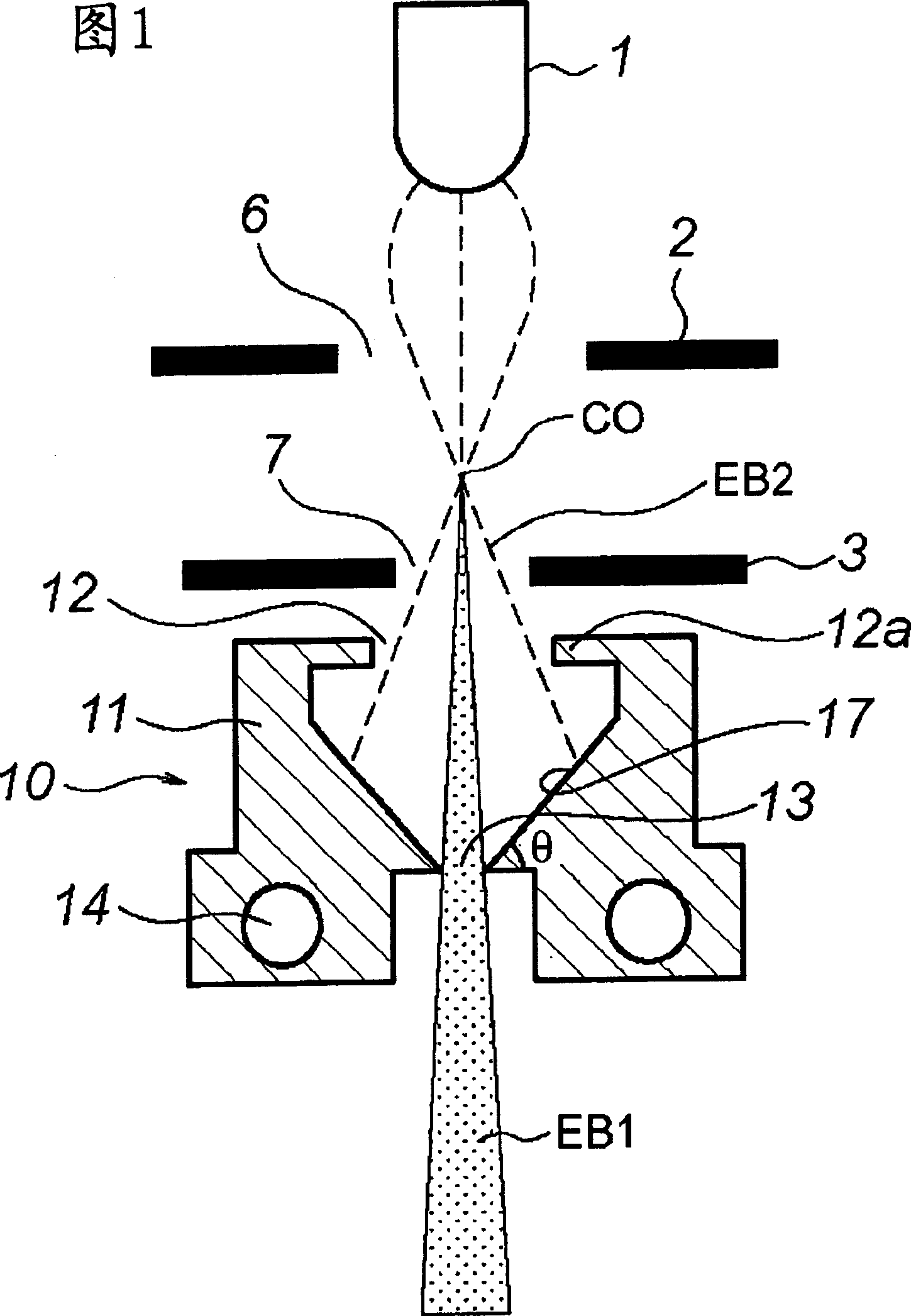
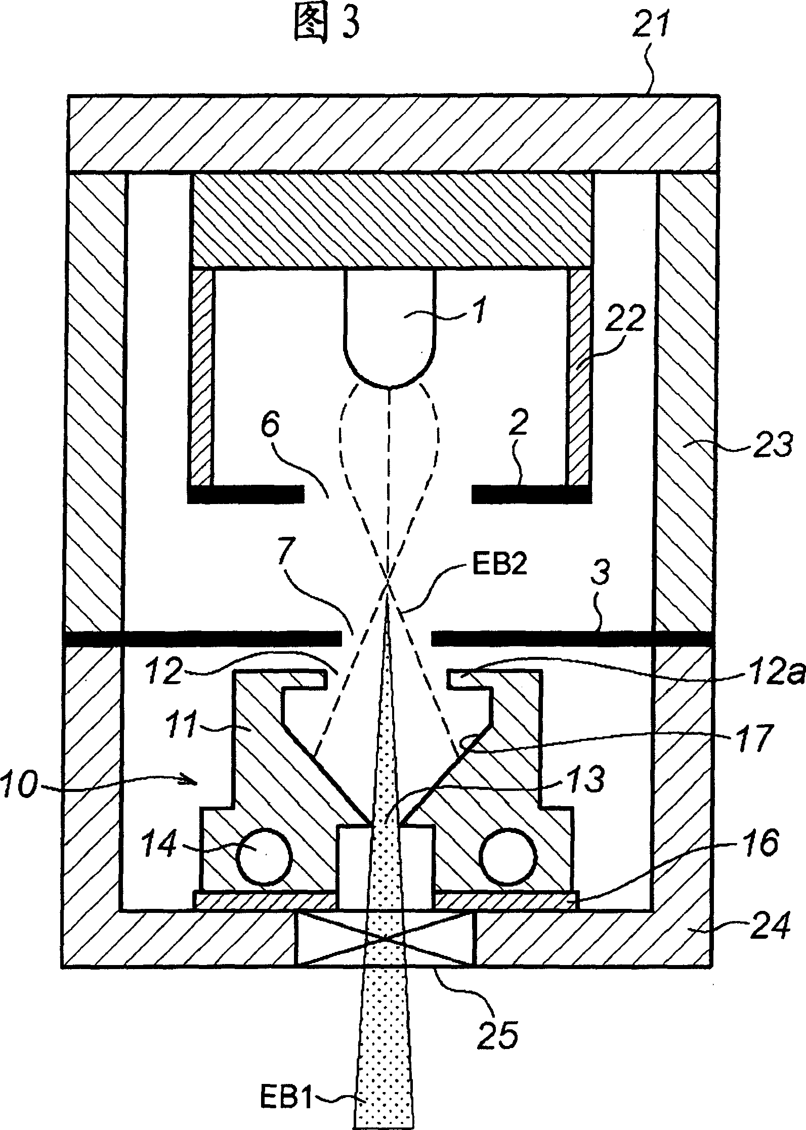
An electron gun includes a cathode portion (1) which emits electrons, an anode portion (3) which accelerates the emission electrons, a bias portion (2) which is arranged between the cathode portion and anode portion and controls trajectories of the emission electrons, a shielding portion (12) which is arranged below the anode portion and shields some of the emission electrons, and a cooling portion (14) which cools the shielding portion.

Description

technical field [0001] The present invention relates to an electron gun used in a photolithography process in the manufacture of a semiconductor device and exposure and patterning techniques using the electron gun. Background technique [0002] In the mass production stage of manufacturing semiconductor devices, optical steppers with high productivity are used, but in the production of storage devices such as 4G DRAM and later with a line width of 0.1 μm or less, as an exposure technology that replaces optical exposure methods, An electron beam exposure method with high image resolution and high productivity is expected. [0003] As conventional electron beam exposure methods, the Gaussian method and the variable shaping method of a single electron beam can be used. [0004] FIG. 9A shows the composition of an exposure apparatus using this conventional electron beam exposure method. The electron beam EB emitted from the front end of the cathode 201 passes through the apertu...

Claims


Application Information

Patent Timeline
Patent Type & Authority Applications(China)
IPC IPC(8): H05H1/24H01J37/06H01J37/065H01J37/09H01J37/305H01L21/027
CPCH01J37/065
Inventor 奧貫昌彦大田洋也
Owner CANON KK
Why Eureka
Eureka Blog
Learn More