Novel hydraulic lift
A hydraulic and elevator technology, which is applied to elevators, transportation and packaging in buildings, can solve the problems of low lifting height, large thrust difference, large installation area, etc., and achieves reduced floor space, low cost, and easy maintenance. convenient effect
- Summary
- Abstract
- Description
- Claims
- Application Information
AI Technical Summary
Problems solved by technology
Method used
Image
Examples
Embodiment 1
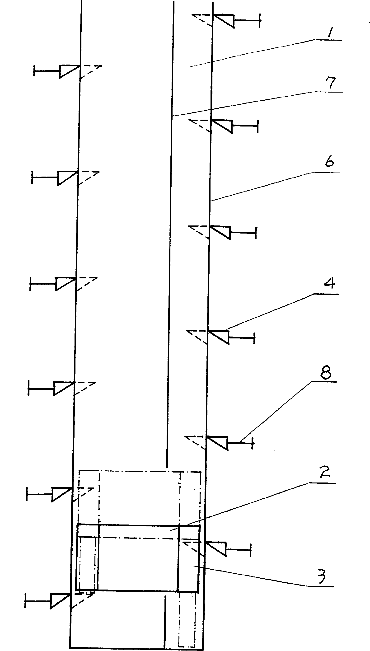
[0020] Example as figure 1 As shown, it is moved with struts 4 while hydraulic cylinders 3 are positioned on the carrying box 2 . The first group of hydraulic cylinder 3 such as figure 1 The right hydraulic cylinder 3 extends the push rod to lift the carrying box 2. When the carrying box 2 rises to a certain height, the second group of pillars 4 can be moved into the underside of the same group of hydraulic cylinders 3. At this time, the pillars are driven. 4. The moving device 8 moves the column 4 under the hydraulic cylinder 3 of the same group to complete the first step. In the second step, the hydraulic cylinder 3 of the second group extends the push rod, the hydraulic cylinder 3 of the first group contracts, and the carrying box 2 rises to the height of the first group of the second section of the pillar 4, the device 8 for driving the pillar 4 to move again Move the struts 4 of the second section of the first group into the underside of the hydraulic cylinders 3 of the...
Embodiment 2
[0021] Example two is as Figure II Shown: it adopts hydraulic cylinder 3 to move and boss 5 to be fixed. The function of the boss 5 is the same as that of the pillar 4 . When the hydraulic cylinders 3 of the first group move to the bosses 5 of the same group under the push of their driving pistons 9 , their push rods extend, the carrying box 2 rises, and reaches the second set of bosses 5 . The piston 9 of the hydraulic cylinder 3 moves it to the second group of bosses 5, its push rod is extended, the carrying box 2 rises again, and when it reaches the third group of bosses 5, the driving piston of the third group of hydraulic cylinders 3 9. Move it to the third group of bosses 5, its push rod extends, and the carrying box 2 rises again. Afterwards, the sequence of each group repeats the cycle alternately, that is, the rise is completed. When descending, the push rods of each group are retracted, that is, they are descending. When the retraction is completed, the moving pi...
Embodiment 3
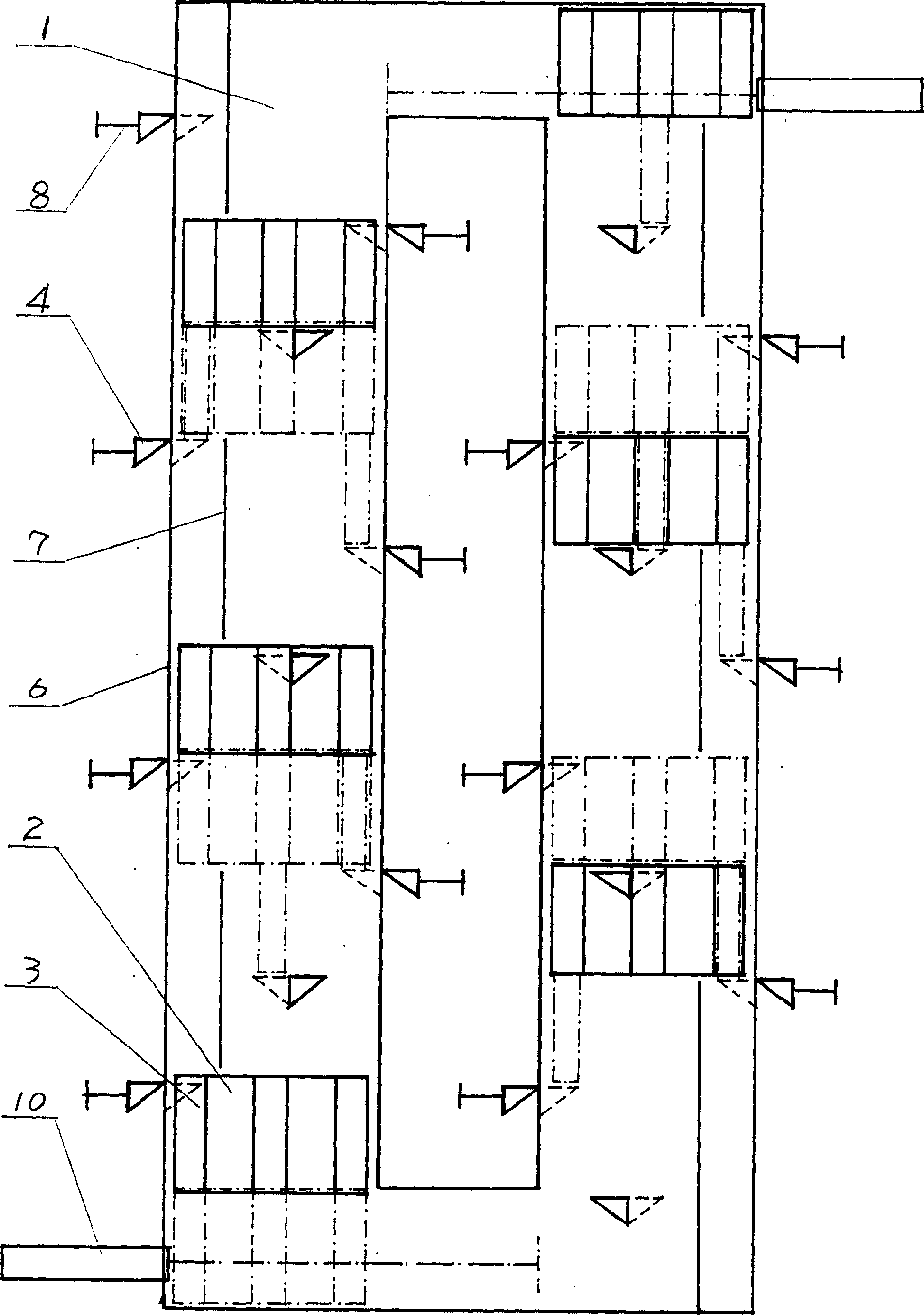
[0022] Example 3 is as image 3 As shown, this example adopts the closed-loop unidirectional motion scheme, and the closed-loop includes dual-channel and network closed-loop. On the channel 1 of the closed circuit, there is at least one carrying box 2 , and a driving device 10 is also provided to drive the carrying box 2 to another channel 1 . The driving device can also be arranged on the carrying box 2 to realize the horizontal or oblique movement of the carrying box 2 to another channel 1 . The principle and function of its scheme are the same as those of expressways and double-track railways, and are suitable for rapid and large-volume use.
PUM
 Abstract
Description
Claims
Application Information
 - Generate Ideas
- Intellectual Property
- Life Sciences
- Materials
- Tech Scout
- Unparalleled Data Quality
- Higher Quality Content
- 60% Fewer Hallucinations
Browse by: Latest US Patents, China's latest patents, Technical Efficacy Thesaurus, Application Domain, Technology Topic, Popular Technical Reports.
© 2025 PatSnap. All rights reserved.Legal|Privacy policy|Modern Slavery Act Transparency Statement|Sitemap|About US| Contact US: help@patsnap.com


