
Coding modulating method and modulator, demodulating method and demodulator, information recording medium

A coding modulation and demodulation technology, applied in data recording, information storage, recording signal processing, etc., can solve the problems of easy continuous occurrence, detection errors, and signal fluctuations, and achieve the effect of less DC components

Inactive Publication Date: 2004-09-22
NEC CORP +1
View PDF3 Cites 3 Cited by
  • Summary
  • Abstract
  • Description
  • Claims
  • Application Information

AI Technical Summary

Problems solved by technology

However, the channel signal bit string modulated by (1, 7) has a high probability that the run length becomes "1", and the 2T pattern (here, T is the channel signal bit length) corresponding to the shortest mark and the shortest space in NRZI recording is easy to continue occur
The continuous reproduction signal of 2T pattern is prone to detection errors caused by PRML
However, Patent Document 3 uses variable-length coding without considering the coding rate
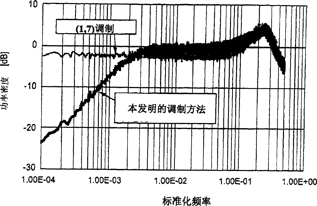
[0010] In addition, when a signal recorded using (1,7) modulation is reproduced from a disc, there is a problem that low frequency components exist in the reproduced signal
If the reproduced signal contains low frequency components, for example, the signal used in the servo control of the disk device will easily fluctuate.

Method used


Image

  • Coding modulating method and modulator, demodulating method and demodulator, information recording medium
  • Coding modulating method and modulator, demodulating method and demodulator, information recording medium
  • Coding modulating method and modulator, demodulating method and demodulator, information recording medium

Examples


Embodiment Construction

[0033] In order to clarify the above and other objects, features, and advantages of the present invention, embodiments of the present invention will be described in detail with reference to the drawings.

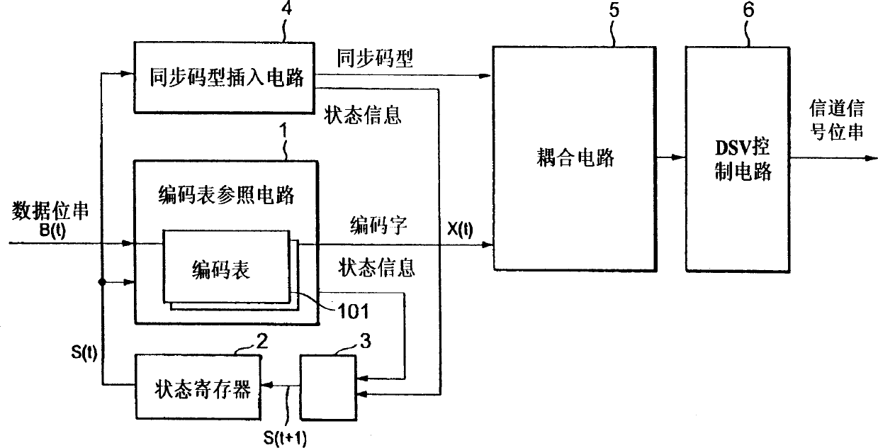
[0034] 1 to 4 show coding tables according to embodiments of the coding and modulation method of the present invention. 1 to 4 generally show three tables corresponding to the 8-bit data words 00 to FF represented in hexadecimal, and the code words of 12 channel signal bits and the values ​​representing the sub-state information S0 to S2. That is, with the coding modulation of the present invention, 8-12 modulation is performed in which 8-bit data words are modulated into 12-bit channel signal bits, and the modulation rate is 2 / 3. The three tables are used when the current state information is in S0, S1, and S2 respectively. The code words of 12 channel signal bits shown in the table use "*" and "#" in addition to "0" and "1". "*" indicates that when the code words are con...


PUM


Abstract

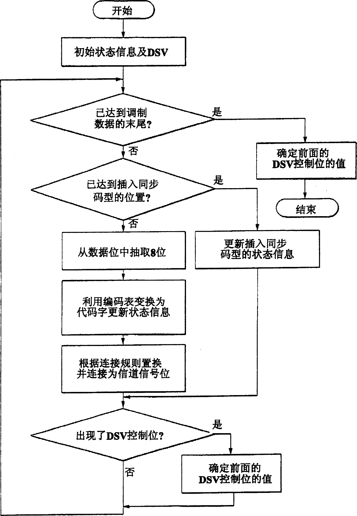
In a code modulating method and a code modulating apparatus, a run length has an encoding rate of 2 / 3 which is equal to that of (1, 7) modulation, and indicates the number of '0' bits between adjacent ones of '1' bits in the channel bit train. A data bit train is converted into the channel bit train so that the run length has a minimum value 1 and a maximum value 10. Further, upon converting any data bit train, the channel bit train does not include a pattern '1010101010101' in which the run length 1 is continuously repeated six times or more. The channel bit train has a DSV (Digital Sum Value) control bit which selects the '0' bit or '1' bit in accordance with a DSV. The channel bit train obtained by using random data for the data bit train is NRZI converted into a signal. A frequency component of the signal is reduced from a maximum value of the frequency component by 20 dB or less as a power density at a frequency of 1 / 10,000 or less of a channel clock frequency.

Description

technical field [0001] The present invention relates to a coding and modulation method, a modulation device, a demodulation method and a demodulation device, and an information recording medium for recording or reproducing digital data on an optical disc. Background technique [0002] When recording data on an optical disc, data modulation is performed to fit the recording medium. When recording and reproducing data on a recording medium, if the recording and reproducing signal contains a DC component, for example, a signal used for servo control of a disk device tends to fluctuate or fluctuate. Therefore, it is best to have as little DC component as possible in the modulated signal. [0003] For example, in DVD (Digital Versatile Disc), according to the run length (RUN LENGTH) limit RLL (2, 10) rule for converting data bit strings into channel signal bit strings, that is, there must be more than two, For less than ten "0", 8-16 modulation is used to modulate an 8-bit data...

Claims


Application Information

Patent Timeline
Patent Type & Authority Applications(China)
IPC IPC(8): G11B20/14G11B27/30H03M7/14
CPCG11B27/3027G11B2220/2562G11B2020/1457G11B20/1426
Inventor 萱沼金司岩永敏明能弹长作
Owner NEC CORP
Learn More