Light mask and diffuse-reflecting board

A technology of diffuse reflection plate and photomask, applied in the direction of diffusion elements, optics, optical elements, etc., can solve the problems of high reflection luminance, difficult quality management, poor repeatability, etc., and achieve the effect of improving reflection luminance

Inactive Publication Date: 2004-09-22
SUMITOMO CHEM CO LTD
View PDF1 Cites 6 Cited by
  • Summary
  • Abstract
  • Description
  • Claims
  • Application Information

AI Technical Summary

Problems solved by technology

The advantage of using these methods is that completely randomly arranged scattering structures can be formed without interference caused by the scattering structures, but it is difficult to obtain high reflection luminance because a specific scattering structure cannot be formed with high precision
In addition, since its configuration is based on natural phenomena, the repeatability is poor and quality control is difficult

Method used


Image

  • Light mask and diffuse-reflecting board
  • Light mask and diffuse-reflecting board
  • Light mask and diffuse-reflecting board

Examples


Embodiment 1

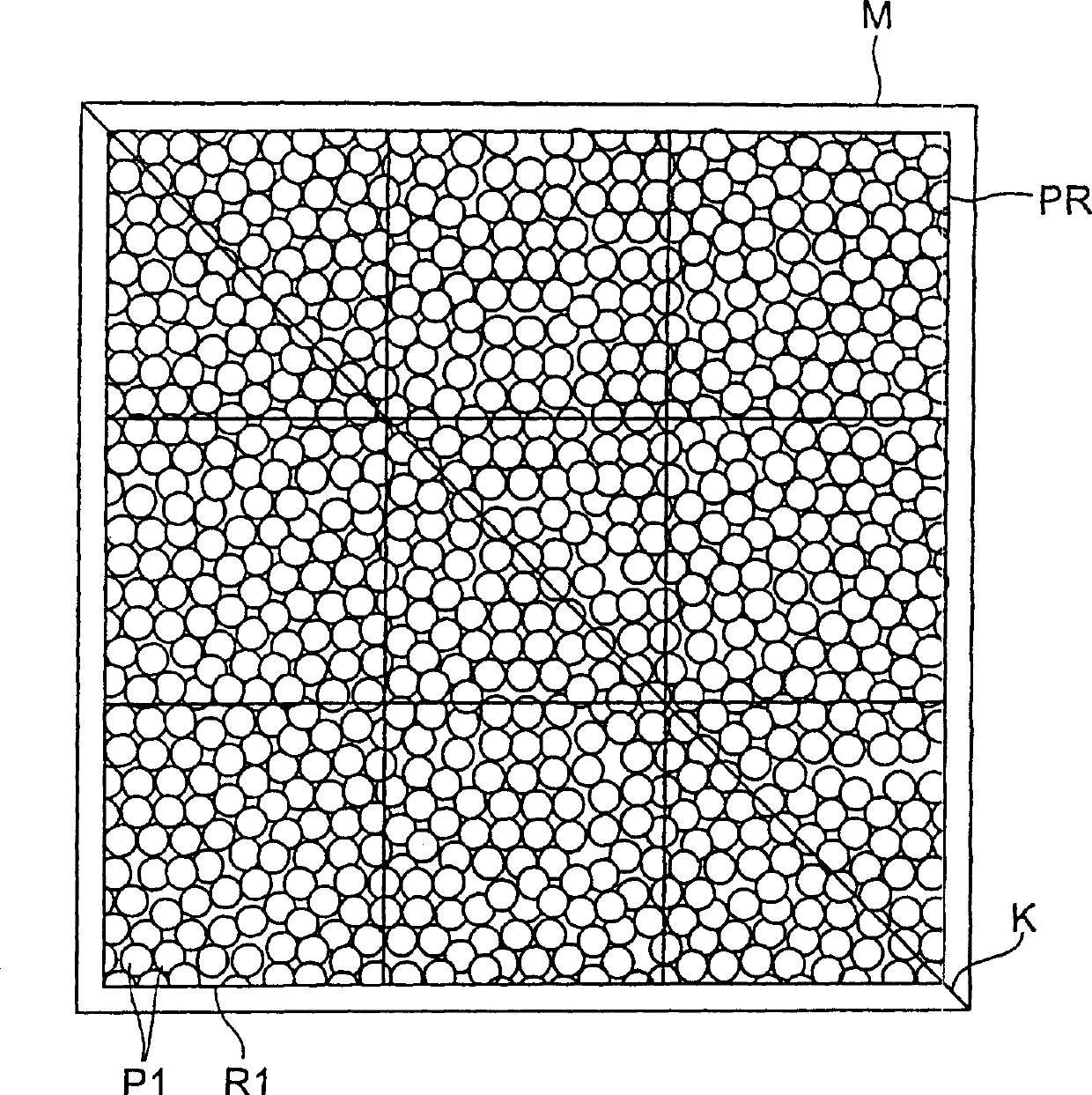
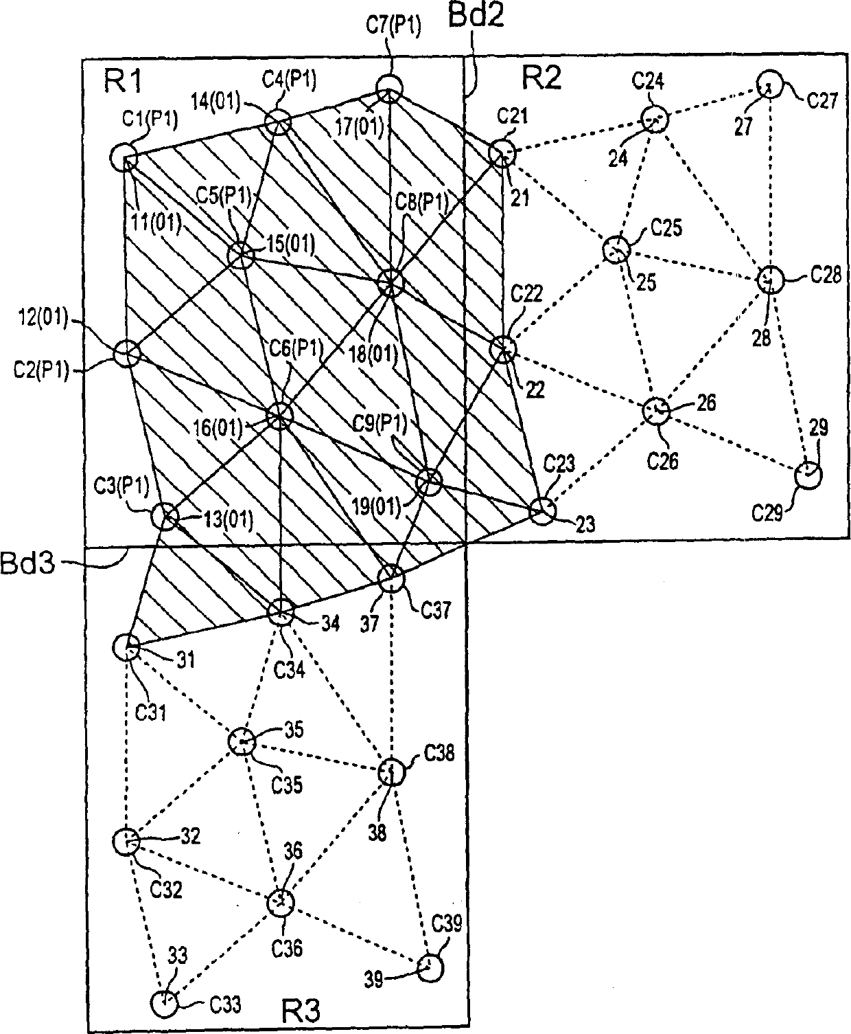
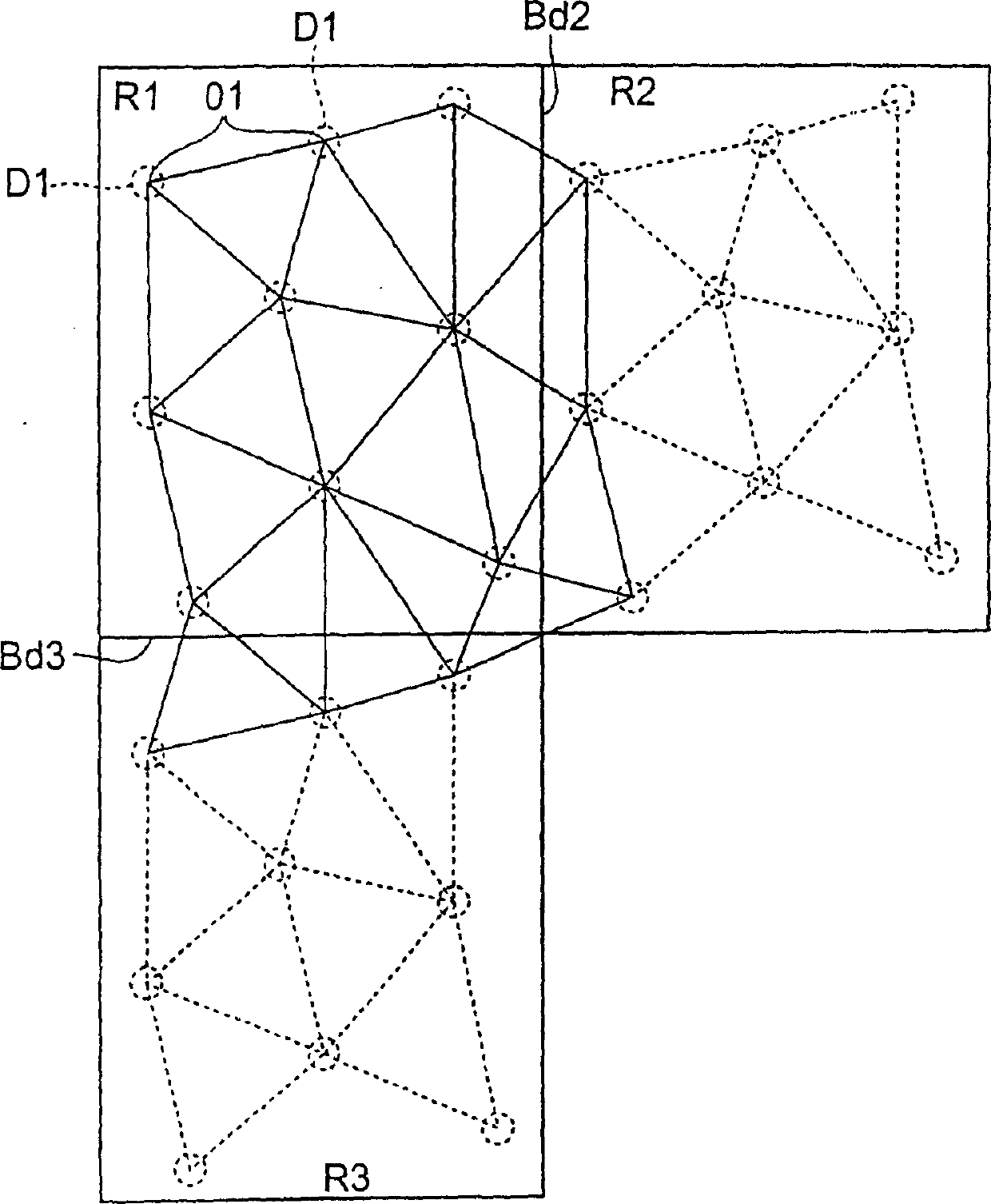
[0104] In the rectangular unit area (66 μm×198 μm) constituting the pattern area of ​​the photomask, center points (73) of circular translucent portions with an outer diameter of 9 μm were arranged in a predetermined arrangement. The configuration is determined by the above method using random numbers. In the resulting configuration, the mean value A prescribed by the Dorronai triangle group (X) is 90 μm 2 , the value of B / A is 0.2. A filter plate with a diffuse reflection plate was fabricated using a photolithography technique realized by proximity exposure using this photomask. In addition, the unit area and the light-transmitting part on the photomask correspond to the unit pixel and the concave-convex part of the color filter.

[0105] First, on a cleaned glass substrate (Corning 1737) of 370×470×0.7 mm, a carbon black-added light-absorbing resist film (transmittance: 0.2 / μm) with a film thickness of 1.1 μm was applied. The resulting resist film was pre-baked on a hot p...

Embodiment 2)~( Embodiment 5

[0114] Within the scope of satisfying the above conditions (1) and (2), change the area of ​​the rectangular unit area, the number of light-transmitting parts, the average value A and B / A, and make a photomask with the pattern area according to the present invention, A diffuse reflection plate was produced in the same process as in Example 1 using this photomask.


PUM

PropertyMeasurementUnit
Transmittanceaaaaaaaaaa

Abstract

PURPOSE: Provided are a photomask capable of producing a diffusion reflector with high reflective luminance without generating interference fringe or speckle, a diffusion reflector, and a color filter. CONSTITUTION: The photomask has a pattern area constituted by repetitively arranging a rectangular, parallelogrammic or hexagonal unit area where center points of a plurality of isolated patterns are arranged. The total area of a plurality of Delaunay triangles constituted by the center points in the unit area and a plurality of Delaunay triangles constituted by crossing over the boundary line of the other unit area adjacent to the unit area satisfies the following conditions: A is not less than 70 micrometer¬2 and not more than 120 micrometer¬2, and B / A is not less than 0.05 and not more than 0.25, wherein A is an average value of the Delaunay triangles having the same unit area, and B is a standard deviation thereof.

Description

field of invention [0001] The invention relates to a photomask and a diffuse reflector. Background technique [0002] A reflective display element that does not require a light source such as a backlight, such as a reflective liquid crystal display element, is a light control means that controls the amount of light incident on the display element and light reflected by the reflector (liquid crystal display element, etc.) Devices that are combined for display are often used in portable devices because they consume less power. [0003] The reflective display element must have a diffuse reflection plate that reflects external light. The diffuse reflection plate scatters the incident external light at an angle of 10-30° away from the normal direction of the diffuse reflection plate, and reflects the scattered light to the observer side. [0004] As a method of manufacturing such a diffuse reflection plate, there is a method of sandblasting a glass or metal plate and smoothing i...

Claims


Application Information

Patent Timeline
IPC IPC(8): G02B5/02G02B5/00G02B5/08G02F1/1335G03F1/00G03F1/70G03F7/20G03F7/207
CPCA43B17/14B29C44/02
Inventor 藤井幸男六原行一
Owner SUMITOMO CHEM CO LTD
Why Eureka
Try Eureka