Triple class E. Doherty amplifier topology for hight efficiency signal transmitters

An amplifier and amplifier circuit technology, which is applied to amplifiers, amplifiers with distributed constants in coupling networks, amplifiers with semiconductor devices/discharge tubes, etc., can solve the problems of output waveform clipping and efficiency drop from peak value, etc.

Inactive Publication Date: 2004-09-15
TELEFON AB LM ERICSSON (PUBL)
View PDF0 Cites 17 Cited by
  • Summary
  • Abstract
  • Description
  • Claims
  • Application Information

AI Technical Summary

Problems solved by technology

However, attempts at this typically result in the power amplifier being "backed-off" from the peak to avoid clipping and distortion of the output waveform
This also results in an associated large drop in efficiency from the peak

Method used


Image

  • Triple class E. Doherty amplifier topology for hight efficiency signal transmitters
  • Triple class E. Doherty amplifier topology for hight efficiency signal transmitters
  • Triple class E. Doherty amplifier topology for hight efficiency signal transmitters

Examples


Embodiment Construction

[0022] Detailed description of the preferred embodiment

[0023] 1. Input Modulation for Envelope Restoration in Class E Amplifiers.

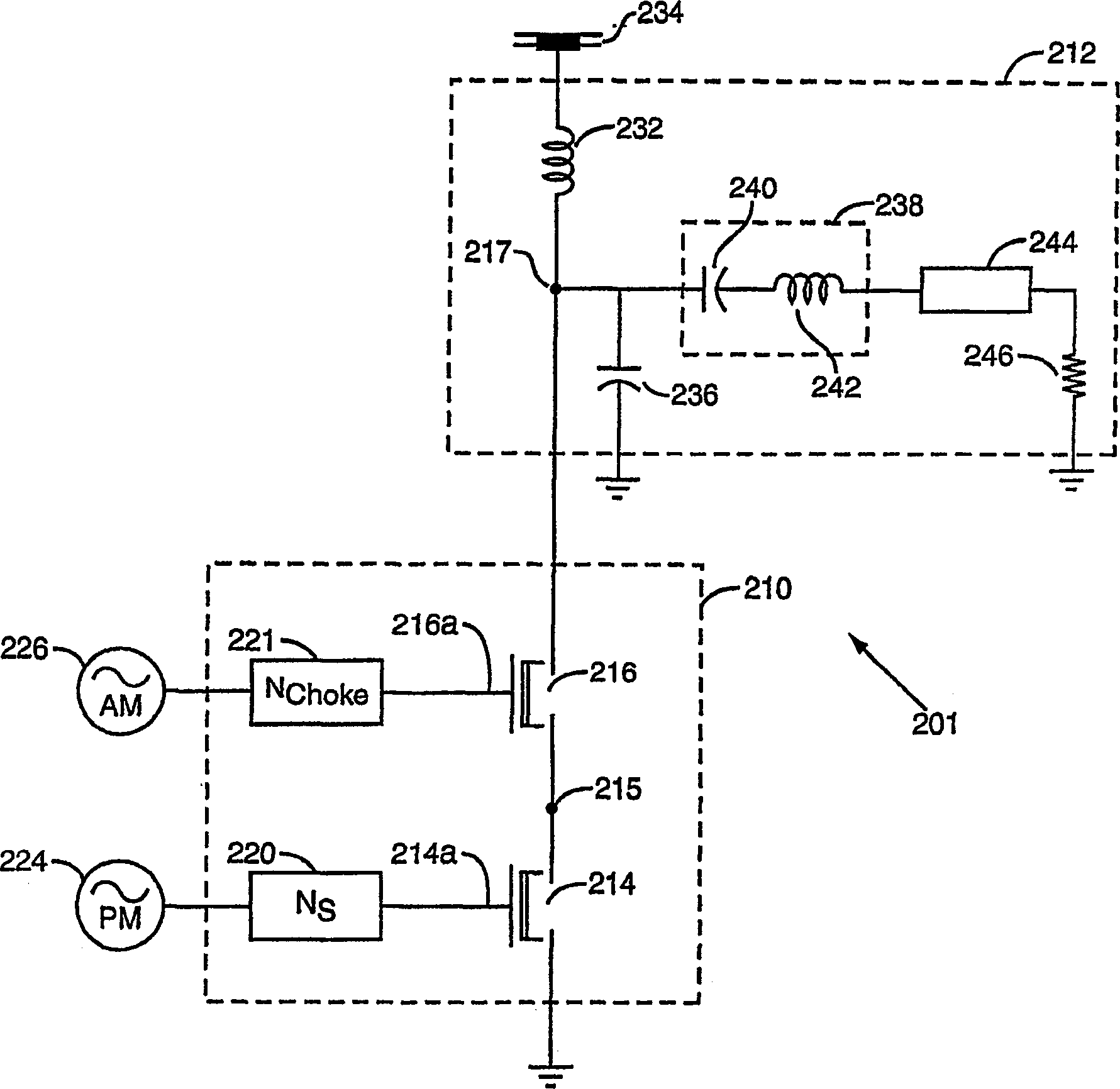
[0024] The various amplifier embodiments mentioned above and disclosed herein involve the use of saturated Class E amplifiers. The input to the amplifier is modulated in various ways in order to vary the output power. Each of these methods can be used here, but for the sake of continuity, the TIMER (transmitter using input modulation for envelope recovery) input modulation scheme is used here as an example in the preferred embodiment. The use of the TIMER scheme in this embodiment involves figure 2 The Class B design shown utilizes a dual-gate FET device as the active switching element. Typically, one switch is driven with only phase constant envelope information, while the other switch is used to modulate the output power envelope. The use of this second envelope termination allows the power amplifier to be switched on indepen...


PUM


Abstract

A Doherty amplifier circuit is provided comprising at least three class E amplifiers (210) receiving separated amplitude (226) and phase information (224) from at least one signal source. At least one first impedance adjustment device is linked between the signal source and the inputs to at least two of the amplifiers, and a plurality of second impedance adjustment devices is linked to the outputs of the amplifiers to combine the outputs into an output of the circuit. In this way, a scheme for efficient amplification of amplitude modulated waveforms is achieved across a wide dynamic range and for a large peak-to-average ratio using only input modulated techniques.

Description

field of invention [0001] The present invention relates to power amplifiers. In particular, the invention relates to the efficient amplification of signals whose envelope is amplitude modulated at off-peak average power levels, and in particular to the application of linear amplification of such signals at RF frequencies up to high power levels. Background of the invention [0002] The requirement for higher data rates and bandwidth efficiency in wireless communication standards has led designers to implement varying envelope modulation formats. Varying AM content in these formats allows additional information to be transmitted in a given bandwidth. This varying envelope greatly constrains the ability of the power amplifier in the wireless device to transmit the waveform linearly. Additionally, the varying envelope exhibits a "peak-to-average" ratio, where the average envelope power may be substantially lower than the peak envelope power. Ideally, a p...

Claims


Application Information

Patent Timeline
Patent Type & Authority Applications(China)
IPC IPC(8): H03F1/02H03F3/217
CPCH03F3/2176H03F1/0288H03F2200/391
Inventor D·R·佩尔克
Owner TELEFON AB LM ERICSSON (PUBL)
Why Eureka
Try Eureka