
Manufacture of micro syringe array

A manufacturing method and technology of needles, applied in the direction of hypodermic injection devices, etc., can solve the problems of complicated production process steps and inability to achieve mass production

Inactive Publication Date: 2004-09-08
IND TECH RES INST
View PDF4 Cites 21 Cited by
  • Summary
  • Abstract
  • Description
  • Claims
  • Application Information

AI Technical Summary

Problems solved by technology

[0006] The technical problem to be solved by the present invention is that the shape and structural strength of the usual microneedle array production process are limited by the production process technology and are not ideal. The existing production process steps are too complicated to meet the reasonable standards for mass production.

Method used


Image

  • Manufacture of micro syringe array
  • Manufacture of micro syringe array
  • Manufacture of micro syringe array

Examples


Embodiment Construction

[0042] 1. Fabrication of microneedle arrays by metal plating

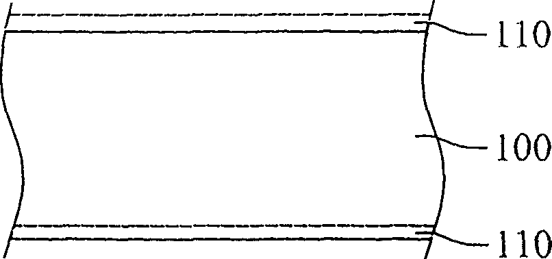
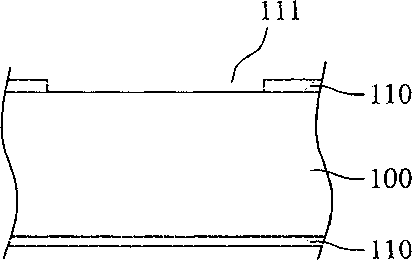
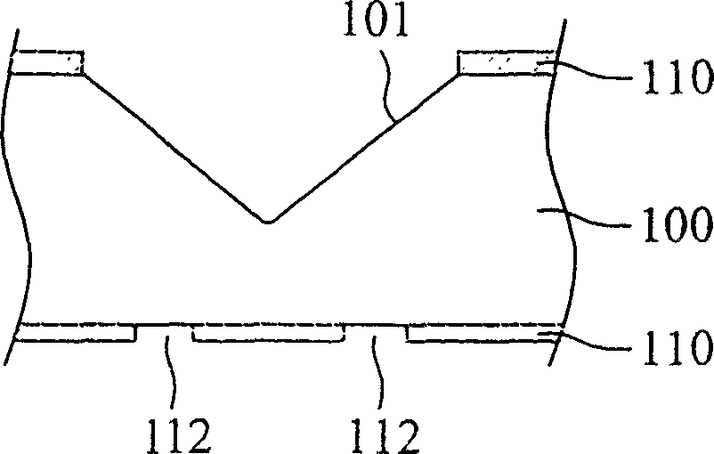
[0043] see Figure 1A to Figure 1H , the manufacturing method of the microneedle array provided by the first preferred embodiment of the present invention is accomplished through the following steps:

[0044] First, a protective layer 110 (such as nitride (Si3N4)) is laid on the upper and lower surfaces of a silicon wafer 100, such as Figure 1A , Figure 1B Lay the photoresist, expose and develop to define the area to be etched, and etch the protective layer 110 to obtain the area to be wet etched 111, and then apply wet etching to the local silicon wafer 110 exposed in the area to be wet etched 111, because the silicon wafer 100 is exposed in the wet etching area 111. The characteristics of anisotropic etching exhibited during etching can form a recessed region 101 with a slope geometry, such as Figure 1C , and then the protective layer 110 on the bottom side also defines the region 112 to be dry etched by lit...


PUM


Abstract

The present invention relates to the manufacture of micro syringe needle array, and the hollow micro needle array with slant end may be manufactured in low cost and simple manufacture process. The micro needles have sharp tip easy to pierce into biological tissue for medicine injection and micro sampling. The manufacture includes wet etching on silicon wafer to form slant notch area, electroplating metal, exposure to develop, micro machining and other steps.

Description

technical field [0001] The invention relates to a method for manufacturing a microneedle, in particular to a method for manufacturing a hollow microneedle array with a beveled end. Background technique [0002] Hollow microneedle arrays (hollow microneedle arrays) are widely used in biomedical fields such as blood collection systems, micro-sampling and drug injection, and their types can be divided into semiconductor materials, polymer materials and metals according to their materials. [0003] At present, semiconductor materials are used to manufacture hollow microneedle arrays, most of which are based on silicon wafers. The manufacturing process disclosed in related patents including WO0215960, WO0217985, WO0166065 and other cases requires multiple dry and wet etching and thin film deposition. Therefore, the manufacturing process is complicated and takes a long time, so that it is difficult to increase the production capacity and reduce the cost, and the road to mass produ...

Claims


Application Information

Patent Timeline
Patent Type & Authority Applications(China)
IPC IPC(8): A61M5/00
Inventor 郭仕奇陈相甫
Owner IND TECH RES INST
Learn More