Eureka AIR delivers breakthrough ideas for toughest innovation challenges, trusted by R&D personnel around the world.

Gasifier of low-temperature liquid

A low-temperature liquid and gasification device technology, applied in household refrigeration devices, gas/liquid distribution and storage, fixed-capacity gas storage tanks, etc., can solve the problem of reduced evaporation capacity of vaporizers, wasteful dissipation of cold energy, and heat transfer temperature differences Large and other problems, to achieve the effect of convenient use and simple installation

Inactive Publication Date: 2004-07-07
TECHNICAL INST OF PHYSICS & CHEMISTRY - CHINESE ACAD OF SCI
View PDF0 Cites 13 Cited by
  • Summary
  • Abstract
  • Description
  • Claims
  • Application Information

AI Technical Summary

Problems solved by technology

Among them, the vaporizer is usually a tube-and-tube heat exchanger. Since the temperature difference in heat exchange is too large when the low-temperature liquid at -162°C is vaporized in the vaporizer, after a period of vaporization, the surface of the vaporizer is covered by cold frost. Covering leads to a reduction in the evaporation capacity of the vaporizer, and this kind of vaporizer has a working time limit, generally no more than 8 hours of continuous work; in addition, the cold energy carried by the cryogenic liquid is dissipated in vain, which cannot produce economic benefits

Method used


Image

  • Gasifier of low-temperature liquid
  • Gasifier of low-temperature liquid
  • Gasifier of low-temperature liquid

Examples


Embodiment 1

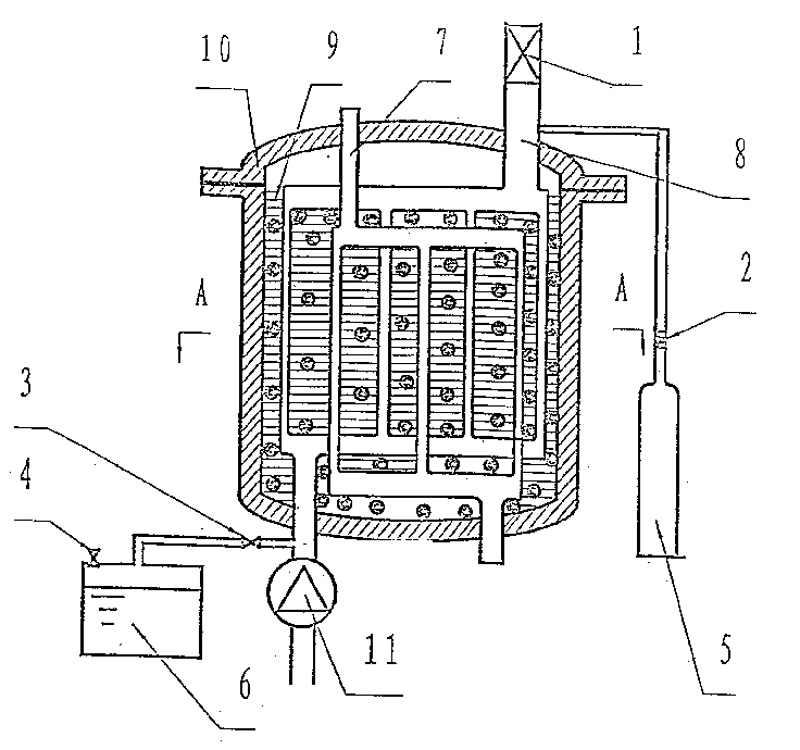
[0014] A gasification device for cold storage cryogenic liquid is made. Such as figure 1 As shown, the device includes: a cryogenic liquid heat exchanger 7, an adiabatic gasification box 10, a refrigerant heat exchanger 8, a cold storage medium 9, a circulation pump 11, an adiabatic storage tank 6 and a nitrogen cylinder 5; wherein, the cryogenic liquid Both the heat exchanger 7 and the refrigerant heat exchanger 8 are fixed in the adiabatic gasification box 10, their inlet pipes are fixed at the bottom of the adiabatic gasification box 10, and their outlet pipes are fixed at the top of the adiabatic gasification box 10, The entire adiabatic gasification box 10 is filled with a cold storage medium 9, the circulation pump 11 is fixedly connected to the inlet pipe of the refrigerant heat exchanger 8, and the heat insulation storage tank 6 is externally connected between the circulation pump 11 and the inlet pipe of the refrigerant heat exchanger 8 , the outlet pipe of the refri...

Embodiment 2

[0017] Utilize the device gasification liquefied natural gas of embodiment 1, concrete steps are as follows:

[0018] (1) The liquefied natural gas in the natural gas heat exchanger 7 gasifies and absorbs heat, and exchanges heat with the cold storage medium 9 on the shell side. The cold storage medium 9 cools down and freezes to release heat. Collected and sent to the gas supply device.

[0019] (2) In the cold storage medium 9 there are water polo with a freezing point of 0°C, salt water polo with a freezing point below zero, and Freon 111 balls with a freezing point of -36.5°C. These phase change balls freeze successively with the continuous cooling of the cold storage medium , to store the intermittent cooling capacity.

[0020] (3) Under the control of the circulating pump-valve linkage mechanism, the cooling capacity is taken out by the refrigerant flowing in the refrigerant heat exchanger 8 with the cold equipment freezer; the specific steps are as follows:

[0021] W...


PUM


Abstract

A cold-accumulating gasifier for low-temp liquid is composed of a low-temp liquid heat-exchanger, an insulating gasifier containing a refrigerant heat-exchanger and a low-temp liquid heat-exchanger and full of cold storing medium, a circulating pump communicated with said refrigerant heat-exchanger and an insulating storage tank, and a nitrogen gas cylinder communicated with said refrigerant heat-exchanger. Its advantages are simple structure and continuous working.

Description

technical field [0001] The invention relates to a low-temperature liquid vaporizer, in particular to a cold storage type low-temperature liquid vaporizer. Background technique [0002] At present, the gas supply device for cryogenic liquid is composed of a cryogenic liquid storage tank, a cryopump, a pressure regulator, a vaporizer, and a gas supply device; It is evaporated into a gaseous state in the carburetor, and then delivered to cryogenic liquid users by the gas supply device. Among them, the vaporizer is usually a tube-and-tube heat exchanger. Since the temperature difference in heat exchange is too large when the low-temperature liquid at -162°C is vaporized in the vaporizer, after a period of vaporization, the surface of the vaporizer is covered by cold frost. Covering leads to a reduction in the evaporation capacity of the vaporizer, and this kind of vaporizer has a working time limit, generally no more than 8 hours of continuous operation; in addition, the cold e...

Claims


Application Information

Patent Timeline
IPC IPC(8): F17C7/04F25D3/10F28D20/00
CPCY02E60/142Y02E60/14
Inventor 杨健慧梁建宁李强李青梁惊涛
Owner TECHNICAL INST OF PHYSICS & CHEMISTRY - CHINESE ACAD OF SCI
Why Eureka
Eureka Blog
Learn More