Eureka AIR delivers breakthrough ideas for toughest innovation challenges, trusted by R&D personnel around the world.

High accurately measuring method for in-tube liquid level elevation of photoelectric and tubular settlement meter

The utility model relates to a water-tube-type sedimentation instrument and a technology for elevation measurement, which is applied in the measurement field and can solve the problems of low precision and large workload, and achieves the effect of simple device and convenient implementation.

Active Publication Date: 2011-05-25
XI AN JIAOTONG UNIV +1
View PDF3 Cites 13 Cited by
  • Summary
  • Abstract
  • Description
  • Claims
  • Application Information

AI Technical Summary

Problems solved by technology

[0003] The purpose of the present invention is to provide a high-precision photoelectric water pipe type sedimentation instrument pipe liquid level elevation measurement method, using parallel light projection method or imaging method to realize the water pipe type sedimentation instrument liquid level change measurement, so as to realize the automatic and non-automatic measurement of the liquid level elevation change Contact high-precision measurement can solve the problems of large workload and low precision of vertical settlement displacement in earth-rock dams or geotechnical engineering

Method used


Image

  • High accurately measuring method for in-tube liquid level elevation of photoelectric and tubular settlement meter
  • High accurately measuring method for in-tube liquid level elevation of photoelectric and tubular settlement meter
  • High accurately measuring method for in-tube liquid level elevation of photoelectric and tubular settlement meter

Examples


Embodiment Construction

[0027] The present invention is described in further detail below in conjunction with accompanying drawing:

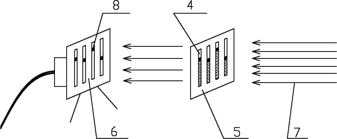
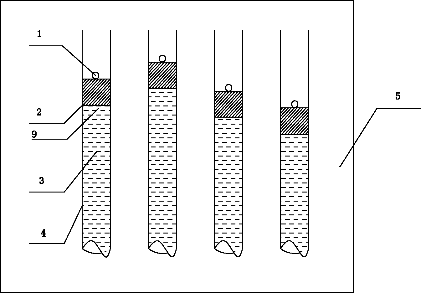
[0028] see figure 1 and figure 2Shown is a schematic diagram of a method, principle and device for measuring the difference in liquid level in a pipe with a water pipe-type sedimentation instrument. It is composed of a light source 1, a float 2, a measuring tube 3 and the liquid 4 inside it, and an observation platform 5, etc. The measuring tube 4 is installed on the observation platform 5, and the measuring tube is connected with the hydraulic tank. The hydraulic tube is an essential part of the settlement instrument. Since all water tube type settlement instruments have this device, it is not shown here. After that, the electric valve can be used to automatically control the liquid addition to the settling side head and the measuring tube in the observation room. After the hydraulic pressure in the measuring tube remains constant, place the float 2 in the measurin...


PUM


Abstract

The invention discloses a measuring method for in-tube liquid level elevation of a photoelectric and tubular settlement meter. In the method, liquid level height variation measurement of a tubular settlement meter is realized by using a parallel light projecting method or an imaging method so as to measure elevation variation of each tested point. In the imaging method, a float on the liquid level is used for spraying a reflective material or a light resource is placed on the float to image on the target surface, and calculation is carried out by extracting the centre of gravity by using the gray gravity method, or liquid level boundary extraction is carried out on the liquid level imaging directly by the image process, so as to realize variation measurement for a plurality of in-tube liquid level elevations; in the projecting method, parallel light for projection is used, and calculation is realized by using projection shadow of the liquid level or the float on a large range linear array photoelectric device for extracting the centre of gravity so as to realize automatic non-contact high accurate measurement of the liquid level elevation variation. The device of the measuring method in the invention is simple in installation and low in cost, and can be widely applied in a vertical settlement shift measuring field of the tubular settlement meter in large-scale buildings and geotechnical engineering, such as an earth and rock dam, a tailings dam and a landslide body and the like.

Description

Technical field: [0001] The invention belongs to the field of measurement, and relates to a height measurement method, in particular to a method for measuring the height of a liquid level in a tube of a high-precision photoelectric water pipe type sedimentation instrument. Background technique: [0002] Due to the fact that there are relatively few methods for measuring the elevation difference of the liquid level in the tube type sedimentation instrument in China at present, it is inconvenient for the staff to measure, and the measurement accuracy is not high enough to achieve accurate measurement of the elevation difference of the liquid level, resulting in the staff working on the There are too many errors in the measurement process of vertical settlement displacement inside earth-rock dams and geotechnical engineering. The measuring method device of the present invention is easy to install, has low cost and high precision, and can be widely used in the vertical settlemen...

Claims


Application Information

Patent Timeline
IPC IPC(8): G01C5/00G01F23/64
Inventor 乐开端黎玮
Owner XI AN JIAOTONG UNIV
Why Eureka
Eureka Blog
Learn More