Method for disk drive
A technology for disk equipment and control circuits, applied in the direction of instruments, support heads, drive/movement recording heads, etc., to solve problems such as large deviation of disk drives, difficult to return safely, and damage to the head assembly.
- Summary
- Abstract
- Description
- Claims
- Application Information
AI Technical Summary
Problems solved by technology
Method used
Image

Examples
no. 1 example
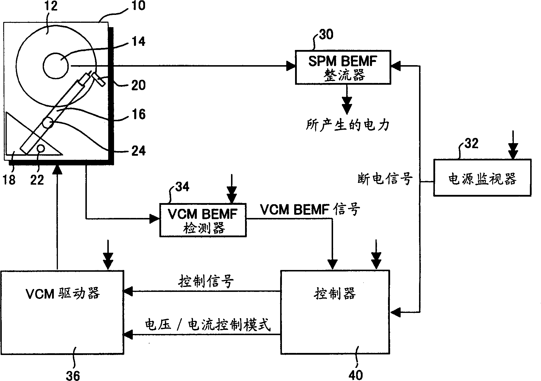
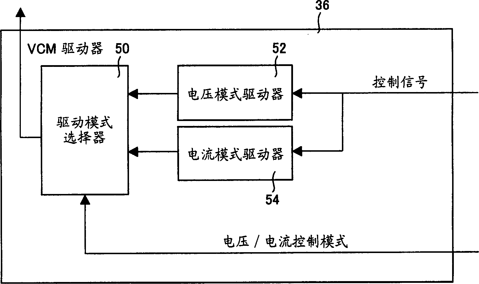
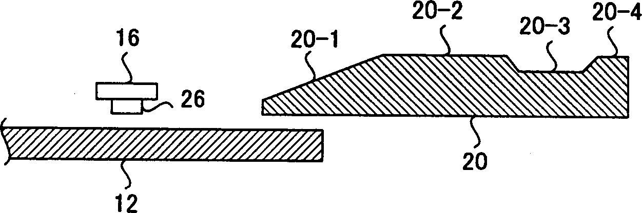
[0058] figure 1 Having described the structure of the first embodiment of the magnetic disk device of the present invention, figure 2 Described figure 1 structure of the VCM driver, image 3 yes figure 1 Sectional view of the arm and ramp in, Figure 4 yes image 3 A top view of the arm and ramp in, Figure 5 Described figure 1 The structure of the controller in .
[0059] Such as figure 1 As shown, a disk drive 10 includes a magnetic disk 12, a spindle motor 14 for rotating the magnetic disk 12, an arm 16 having a head slider at the top, and a VCM (sound) for moving the arm 16 containing the head slider in the radial direction of the magnetic disk 12. circle motor) 18, and a ramp 20 provided on the outer circumference of the magnetic disk 12, on which the arm 16 retracts.
[0060] The VCM 18 includes a fixed magnet and a drive coil provided at the rear end of the arm 16 . The arm 16 includes a swing arm that rotates around a rotation axis 24 and an inner stoppe...
no. 2 example
[0090] Figure 9 The structure of the second embodiment of the disk drive of the present invention is described, Figure 10 Described Figure 9 The structure of the VCM driver in.
[0091] exist Figure 9 and Figure 10 in, with figure 1 The same components are denoted by the same reference numerals. In other words, if Figure 9 As shown, a disk drive 10 includes a disk 12, a spindle motor 14 that rotates the disk 12, an arm 16 with a head slider at its tip, and a VCM (Voice Coil Motor) for moving the arm 16 containing the head slider in the radial direction of the disk 12. 18, and a ramp 20 provided on the outer circumference of the disk 12, on which the arm 16 retracts.
[0092] The VCM 18 includes a fixed magnet and a drive coil provided at the rear end of the arm 16 . The arm 16 includes a swing arm that rotates around a rotation shaft 24 , and an inner stopper 22 for limiting the inner circumferential position of the arm 16 is provided on the VCM 18 . The struct...
no. 3 example
[0115] Figure 13 Having described the structure of the third embodiment of the magnetic disk device of the present invention, Figure 14 Described Figure 13 structure of the VCM driver, Figure 15 Described Figure 13 The structure of the local controller in .
[0116] exist Figure 13 in, with figure 1 and Figure 9 The same components are denoted by the same reference numerals. In other words, if Figure 13 As shown, a disk drive 10 includes a disk 12, a spindle motor 14 that rotates the disk 12, an arm 16 having a head slider at its tip, and a VCM (Voice Coil Motor) for moving the arm 16 including the head slider in a radial direction of the disk 12. 18, and a ramp 20 provided on the outer circumference of the disk 12, on which the arm 16 retracts.
[0117] The VCM 18 includes a fixed magnet and a drive coil provided at the rear end of the arm 16 . The arm 16 includes a swing arm that rotates around a rotating shaft 24 , and an inner stopper 22 for limiting the...
PUM
 Abstract
Description
Claims
Application Information
 - R&D
- Intellectual Property
- Life Sciences
- Materials
- Tech Scout
- Unparalleled Data Quality
- Higher Quality Content
- 60% Fewer Hallucinations
Browse by: Latest US Patents, China's latest patents, Technical Efficacy Thesaurus, Application Domain, Technology Topic, Popular Technical Reports.
© 2025 PatSnap. All rights reserved.Legal|Privacy policy|Modern Slavery Act Transparency Statement|Sitemap|About US| Contact US: help@patsnap.com