Log splitting and unloading machine for wood processing

A log and wood technology, applied in the field of log splitting and unloading machinery for wood processing, can solve the problems of unloading of logs that cannot be stacked one by one, change of log angle, and inability to provide preliminary assistance for peeling operations, etc.

Active Publication Date: 2022-05-24
徐州美邦木业有限公司
View PDF0 Cites 0 Cited by
  • Summary
  • Abstract
  • Description
  • Claims
  • Application Information

AI Technical Summary

Problems solved by technology

[0002] The log is cut into a certain length of wood according to the size, shape, quality standard or special regulations. This piece of wood is called a log. When logging the log, it is necessary to use an unloading machine to carry out the log from top to bottom one by one. The unloading and transshipment of logs enables subsequent processing of logs, but at the same time, the existing log unloading and transshipment equipment also has the problems of inconvenient unloading of logs and slipping of logs during unloading
[0003] Based on the existing problems, the existing log unloading and transshipment equipment has the following disadvantages: 1. The existing equipment unloads the logs one by one from top to bottom by hoisting, and it is easy to affect many logs during the unloading process. , so that the position of other unloaded logs will move, which will affect the next unloading, and the angle will change when the logs are hoisted, which needs to be manually corrected. Grabbing from the side makes the operation more complicated and affects the efficiency of log unloading
[0004] 2. When unloading the logs one by one, the stacked logs cannot be unloaded one by one smoothly. The existing equipment is not efficient when unloading. At the same time, it needs to be unloaded from the top of the stack. The working range of the equipment is large. , high unsafe factors
[0005] 3. The logs with bark need to be peeled after being transshipped. The existing log transshipment equipment cannot provide preliminary assistance for the subsequent peeling operation.

Method used


Image

  • Log splitting and unloading machine for wood processing
  • Log splitting and unloading machine for wood processing
  • Log splitting and unloading machine for wood processing

Examples


Embodiment Construction

[0030] The technical solutions in the embodiments of the present invention will be clearly and completely described below with reference to the accompanying drawings in the embodiments of the present invention. Obviously, the described embodiments are only a part of the embodiments of the present invention, but not all of the embodiments. Based on the embodiments of the present invention, all other embodiments obtained by those of ordinary skill in the art without creative efforts shall fall within the protection scope of the present invention.

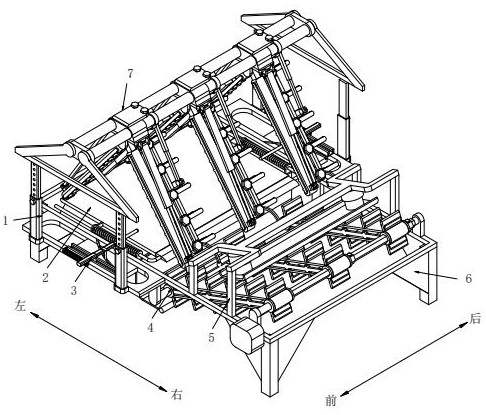
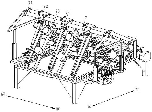
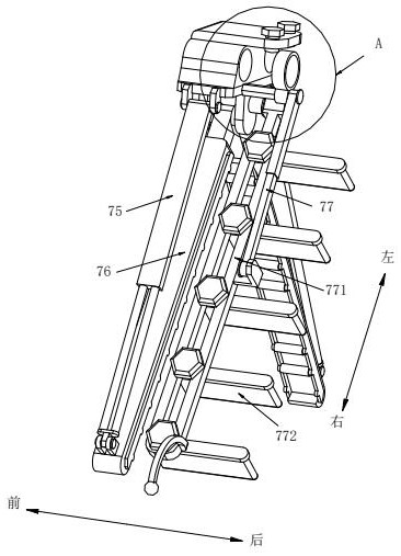
[0031] see Figure 1-Figure 10 , a log material unloading machine for wood processing, comprising a support base 6, the left position of the front and rear surfaces of the support base 6 is symmetrically fixed and connected to the limit assembly 3, and the two limit assemblies 3 are left and right on the side away from the support base 6. A telescopic adjustment rod 1 is symmetrically and fixedly connected, the top ends of the four te...


PUM


Abstract

The invention relates to the technical field of wood processing equipment, in particular to a log splitting and unloading machine for wood processing. The left side of the front and rear surfaces of the support seat are symmetrically fixedly connected to the limit assembly, and the two limit assemblies are far away from the support seat. One side of each side is symmetrically fixedly connected with telescopic adjustment rods, and the top ends of the four telescopic adjustment rods are jointly connected with a clamping assembly, and the right side of the upper surface of the support base is fixedly connected with a conveying assembly. The pressure component is fixedly connected to the surface and above the conveying component. After the log is placed on the unloading component, multiple groups of left-right symmetrical clamping strips limit the left and right directions of the log, so that when the log is unloaded one by one, It will not be confused together. The hydraulic cylinder gradually pushes the logs through the telescopic push plate, so that the logs that are stacked as a whole are stressed at the same time when the logs are unloaded. When the telescopic push plate pushes the logs, the logs move more smoothly.

Description

technical field [0001] The invention relates to the technical field of wood processing equipment, in particular to a log material dividing and unloading machine for wood processing. Background technique [0002] Logs are wood segments that are cut into a certain length according to the standard or special regulations of size, shape, and quality. However, the existing log unloading and transfer equipment also has the problems of inconvenient log unloading and log slipping during the unloading process. [0003] Based on the existing problems, the existing log unloading and transfer equipment has the following shortcomings: 1. The existing equipment unloads the logs one by one by lifting them from top to bottom, and it is easy to affect multiple logs during the unloading process. , so that the position of other unloaded logs will move, which will affect the subsequent unloading, and the angle will change when the logs are hoisted, which requires manual righting. At the same ti...

Claims


Application Information

Patent Timeline
Patent Type & Authority Patents(China)
IPC IPC(8): B65G47/82B27M1/00
Inventor 陈帅帅
Owner 徐州美邦木业有限公司
Why Eureka
Try Eureka