Shaft type speed variator with planetary gear transmission

A technology of planetary gears and transmissions, used in gear transmissions, transmissions, belts/chains/gears, etc.

Inactive Publication Date: 2004-06-02
OECHSLER AG
View PDF3 Cites 0 Cited by
  • Summary
  • Abstract
  • Description
  • Claims
  • Application Information

AI Technical Summary

Problems solved by technology

This is a rather expensive construction, where higher demands are placed on the quiet operation of the transmission

Method used


Image

  • Shaft type speed variator with planetary gear transmission
  • Shaft type speed variator with planetary gear transmission

Examples


Embodiment Construction

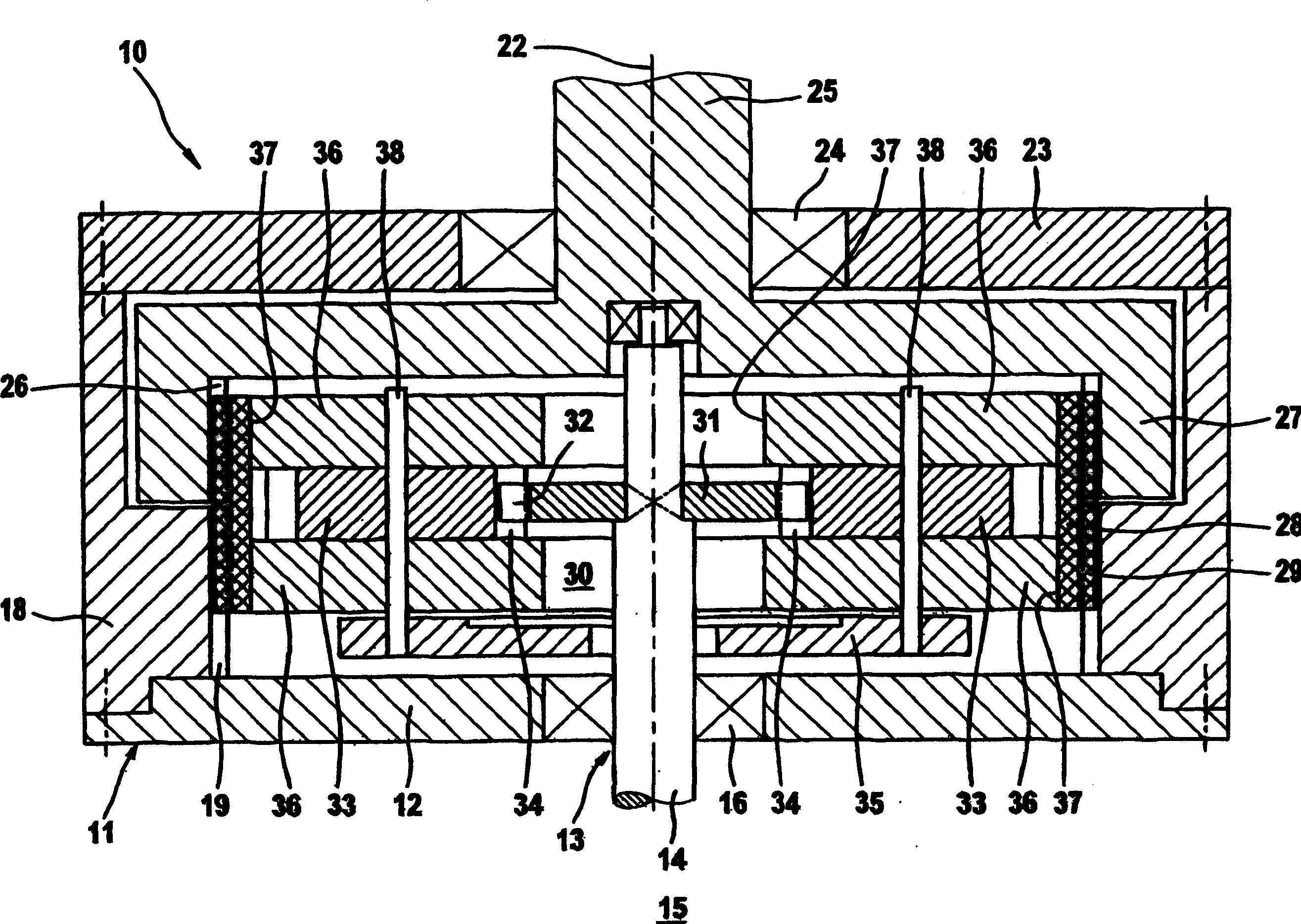
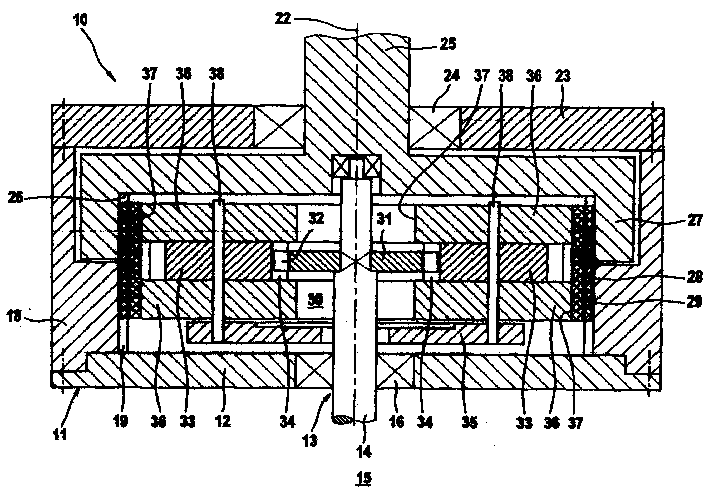
[0012] The axial transmission 10 designed according to the invention, which can be completely injection-molded from plastic, is shown in a schematic axial profile in the drawing and has a housing 11 with an approximately disc-shaped base plate 12 . A central through-hole 13 is used to insert the drive shaft 14 , which can directly be the main shaft of the drive motor 15 . The diameter of the bore 13 is greater than the diameter of the shaft 14 , so that there is no radial bearing function here, since this function is assumed by the motor bearing 1 . Otherwise, or when the base plate 12 is the bearing cover of the motor 15 , the hole 13 is equipped with a bearing 16 . In contrast, the drive shaft 14 is mounted, as shown in the sketch, in a bearing-mounted output shaft 25 in order to avoid bending stresses.

[0013] In the illustrated embodiment, the base plate 12 has a profiled design at its edge in order to positively accommodate a support ring 18 fixed to the housing, which ...


PUM


Abstract

In the toothing between the sun wheel fixed to the driving side to planetary gear, the rotation speed of the driving shaft is first reduced in a structure capable of being subdivided and then further reduced greatly in a typical shaft type speed variator from the ligament to outer ring teeth. There is no tooth mesh in planetary drive unit for input reduction and the speed variator casing, so that the rolling of the planetary roller used as wave generator and planetary gear connector on the inner surface of the ligament has the effect as reliable overload sliding shaft coupling in the force flow beside overload protection in friction form between each of the planetary gears and each of the planetary rollers on two sdies. The rolling has no jamming and is smooth, especially in case of smaller input speed and force linking rather than shape linking.

Description

technical field [0001] The invention relates to a shaft transmission as stated in the preamble of the main claim. Background technique [0002] Such a transmission is known from DE 197 08 310 A1, also known as an endless belt transmission, with a wave generator (Wellgenerator), which is in the form of a non-circular core or a disk rotating eccentrically to the drive shaft, the disk along the It rolls against the inner surface of the ligament, where the ligament is also referred to as a radially elastic rolling bush. Each disc is rotatably supported on a rotating plate which does not rotate relative to the drive shaft. But if an input reduction is required prior to the true shaft transmission, the discs described in any of the prior publications refer to planetary gears meshing on a sun gear which is non-rotatably coupled to the drive shaft. This necessarily results in undesirably high, wear-inducing and noisy stresses on the inner surfaces of the ligaments caused by the to...

Claims


Application Information

Patent Timeline
Patent Type & Authority Applications(China)
IPC IPC(8): F16H3/44F16H25/06
Inventor M·鲁托尔F·佩劳
Owner OECHSLER AG
Why Eureka
Try Eureka