
Circuit marking method for medical ambi-plasma cutting head

A technology of plasma and cutting head, which is applied in the field of circuit identification of plasma cutting head, can solve the problems of capacitor breakdown, poor electric pulse impact ability, unreliable power source measurement identification value, etc., and achieve strong electric pulse impact ability, The effect of reliable measurement identification value and accurate and reliable measurement

Inactive Publication Date: 2004-04-28
SCANMED CHINA
View PDF0 Cites 6 Cited by
  • Summary
  • Abstract
  • Description
  • Claims
  • Application Information

AI Technical Summary

Problems solved by technology

[0004] At present, there is a product on the market that uses a capacitor to mark the code of the cutting head, but the power source is not reliable enough to measure the mark value, the measurement accuracy is affected by the leakage factors such as the humidity of the connector, and the ability to accept external electric pulse impact is poor. , often breakdown the capacitor

Method used


Image

  • Circuit marking method for medical ambi-plasma cutting head
  • Circuit marking method for medical ambi-plasma cutting head
  • Circuit marking method for medical ambi-plasma cutting head

Examples


Embodiment 1

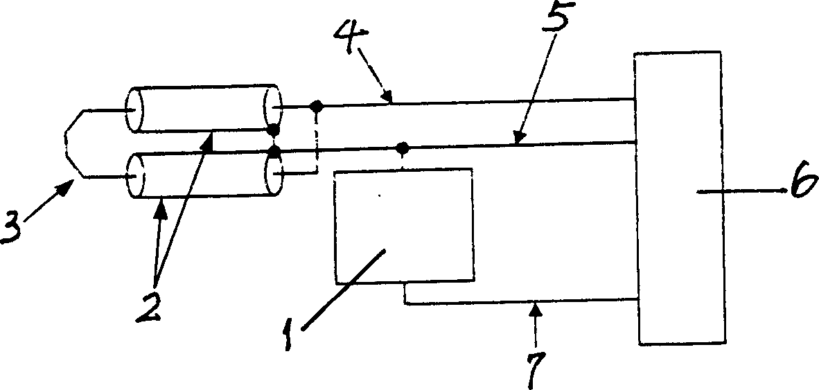
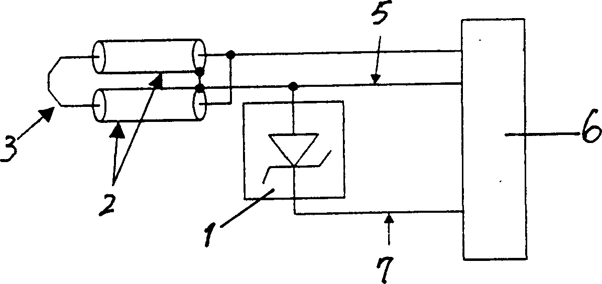
[0023] Example 1, such as figure 2 An example of using a Zener diode as a two-port voltage regulator is given. The anode of the Zener diode is connected to the cut outer electrode. During online measurement, when the power source flows positive current into the negative pole of the Zener diode, measure its steady voltage value, and after quantification, the model code of the cutting head can be determined. When the power source flows negative current into the negative pole of the Zener diode, the measured voltage value is the forward voltage drop value of the diode.

Embodiment 2

[0024] Example 2, such as image 3 Gives another example of using a Zener diode as a two-port voltage regulator, and the negative pole of the Zener diode is connected to the cutting external electrode. During online measurement, when the power source flows negative current into the positive pole of the Zener diode, measure its voltage stabilization value, and after quantification, the model code of the cutting head can be determined. When the power source flows positive current into the negative pole of the Zener diode, the measured voltage value is the forward voltage drop value of the diode.

Embodiment 3

[0025] Example 3 as Figure 4 An example of using two Zener diodes in reverse series as a two-port voltage stabilizer, the negative poles of the two Zener diodes are connected together, and the positive pole of one Zener diode is connected with the cutting external electrode is given. During online measurement, when the power source flows positive current into the marked electrode, measure the D1 steady voltage value plus the forward voltage drop of D2; when the power source flows negative current into the marked electrode 8, measure the D2 steady voltage value plus D1’s positive pressure drop. According to the measured two sets of voltage values, the model code can be determined after quantification. Since there are two sets of voltage values, more coding combinations can be formed.


PUM


Abstract

The present invention provides circuit marking method of medical ambiplasma cutting head and features the two-port voltage stabilizing device, which has one end connected to the medical ambiplasma cutting outer electrode and the cutting head connector, and the other end connected to the cutting head connecting line via marking connecting line; and the internal cutting electrode connected to the cutting head connector. The present invention, as one advanced and effective circuit marking method, has accurate and reliable measuring mark value, measuring precision not affected by the moisture and electric leakage factors and high electric pulse impact resistance.

Description

Technical field [0001] The invention relates to a circuit marking method, in particular to a circuit marking method of a medical bipolar plasma cutting head. Background technique [0002] The bipolar plasma cutting head is a surgical instrument used for electrosurgical treatment of patients with a bipolar high-frequency power source, such as the treatment of benign prostatic hyperplasia and other diseases. Two modes of tissue action are produced by adjusting the power of the high-frequency power source. The first mode will generate an ionized plasma halo in the active area of ​​the tissue treatment electrode, and the tissue entering the high-energy plasma halo will be vaporized instantly, and then rinsed with irrigating fluid. Lose. In the second mode, tissue temperature can be raised rapidly, predictably, and in a controlled manner to melt tissue or seal blood vessels. There are many types of cutting heads for different purposes. [0003] Since the source acting on the b...

Claims


Application Information

Patent Timeline
IPC IPC(8): A61B18/04A61B18/08A61B18/14
Inventor 林敏孙国良王沐刘忠礼
Owner SCANMED CHINA
Learn More