Optical method for detecting discerptible medium skin layer and deep layer information
A separation medium and optical detection technology, applied in the field of optical detection, can solve problems affecting the accuracy of measurement results
- Summary
- Abstract
- Description
- Claims
- Application Information
AI Technical Summary
Problems solved by technology
Method used
Image

Examples
Embodiment 1
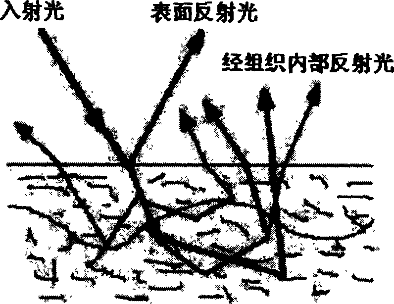
[0042] In this experiment, a complete verification experiment method is designed for the principle of the optical detection method of the above-mentioned separable medium surface and deep layer information. In this experiment, fresh pigskin is used as the experimental sample, and the specular reflection component and the backscattered light component in the reflected light are studied separately by using the light blocking method. The experiment proves that when the linearly polarized light is used as the light source, the specular reflection component remains The original polarization state, but the backscattered light entering the tissue after multiple scattering events will lose its polarization state and become unpolarized light, thus verifying the realization principle of the polarization method. In addition, the experiment also verified the realization principles of the light blocking method and the Brewster's angle method.
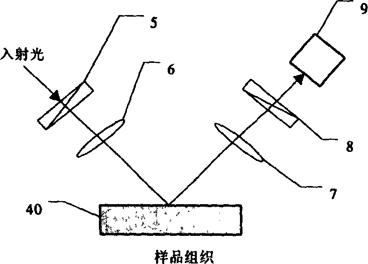
[0043] Experimental device such as Figure 7...
Embodiment 2
[0065] Embodiment 2: Polarization method embodiment
[0066] This embodiment uses the polarization method to eliminate the reflected light on the surface of the tissue, and realizes the non-contact spectroscopic measurement of the components in the human body, especially the non-invasive measurement of the blood sugar of the human body. Measuring devices such as Figure 9, the experimental object is the palm of a volunteer, and the spectral measurement is completed by an FT spectrometer 20 (Spectrum GX FTIR spectrometer, Perkin-Elmer Inc.), using a 250W bromine tungsten lamp as the external light source 32, which is input into the FT through the lens 33, and then After the FT is split, it is transmitted to the reflector 21, and then coupled to the near-infrared light-guiding fiber 23 through the converging lens 22, and the light output from the fiber is converged to the palm 41 of the measured part through the lens 24 and the polarizer 34. The reflected light is coupled into ...
Embodiment 3
[0068] Embodiment 3: embodiment of light blocking method
[0069] In this embodiment, the light-shielding method is used to eliminate the reflected light on the surface of the tissue, and the non-contact spectroscopic measurement of the components in the human body, especially the non-invasive measurement of the blood sugar in the human body is realized. Measuring devices such as Figure 11 , the system uses AOTF as the optical splitting device 42 . The system light source 32 adopts a 250W halogen tungsten lamp, which is incident on the AOTF crystal through the lens 33. The AOTF crystal is driven by the radio frequency drive module 37 controlled by the computer 38, and realizes the spectroscopic scanning of the input light. The split light is coupled into the light guide fiber 23 through the converging lens 22 , and then converged to the measured part (palm 41 ) through the lens 24 . The light blocking sheet 26 eliminates the surface reflected light, and the reflected light ...
PUM
| Property | Measurement | Unit |
|---|---|---|
| thickness | aaaaa | aaaaa |
Abstract
Description
Claims
Application Information
 - Generate Ideas
- Intellectual Property
- Life Sciences
- Materials
- Tech Scout
- Unparalleled Data Quality
- Higher Quality Content
- 60% Fewer Hallucinations
Browse by: Latest US Patents, China's latest patents, Technical Efficacy Thesaurus, Application Domain, Technology Topic, Popular Technical Reports.
© 2025 PatSnap. All rights reserved.Legal|Privacy policy|Modern Slavery Act Transparency Statement|Sitemap|About US| Contact US: help@patsnap.com