In-vehicle body detection method
A technology for vehicles and the human body, applied in the direction of measuring devices, detection with electromagnetic waves, diagnostic recording/measurement, etc., to achieve the effect of energy saving
- Summary
- Abstract
- Description
- Claims
- Application Information
AI Technical Summary
Problems solved by technology
Method used
Image
Examples
Embodiment 1
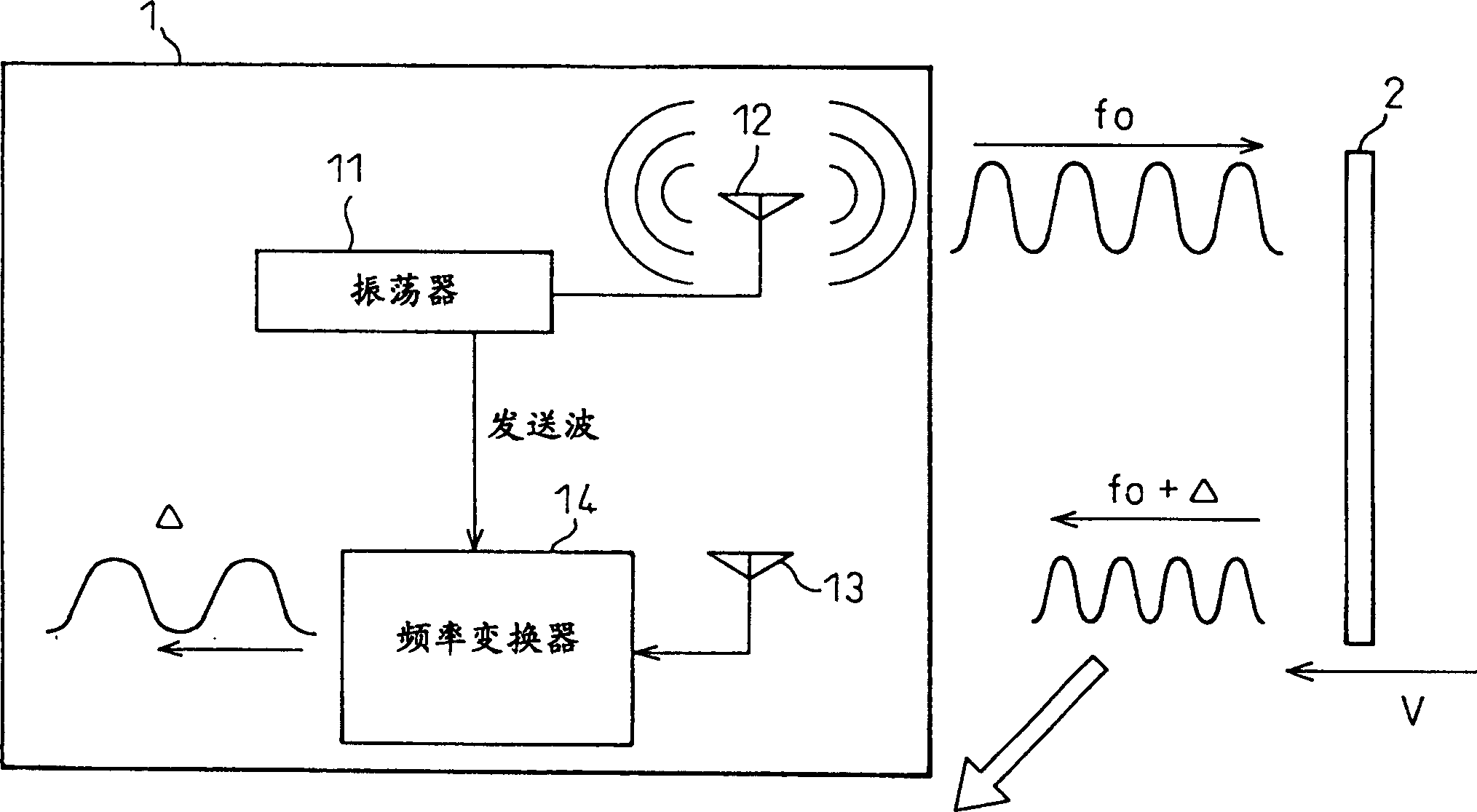
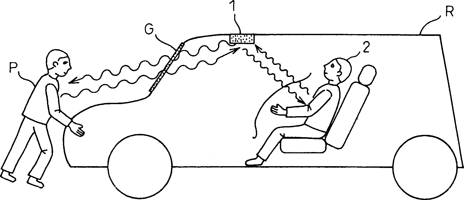
[0062] In the case of a person in the vehicle, due to his breathing movement, oscillations are generated in the reflected waves of the microwaves emitted from the sensor. As described above, if high-frequency microwaves are used, there is no influence on the movement outside the vehicle, and there is a possibility of detecting it when there is a large movement outside the vehicle. However, detection is single-shot as movement outside the vehicle, such as when pedestrians pass by. On the other hand, breathing motion is continuously detected when there is a person in the vehicle. Therefore, it can be determined that a human body is present in the vehicle when vibrations are continuously generated in the reflected waves of microwaves for a long time, for example, several minutes. On the other hand, when this is not the case, it can be seen as movement outside the car.
[0063] Figure 13 is a flowchart illustrating an embodiment of the inventive method based on the above consi...
Embodiment 2
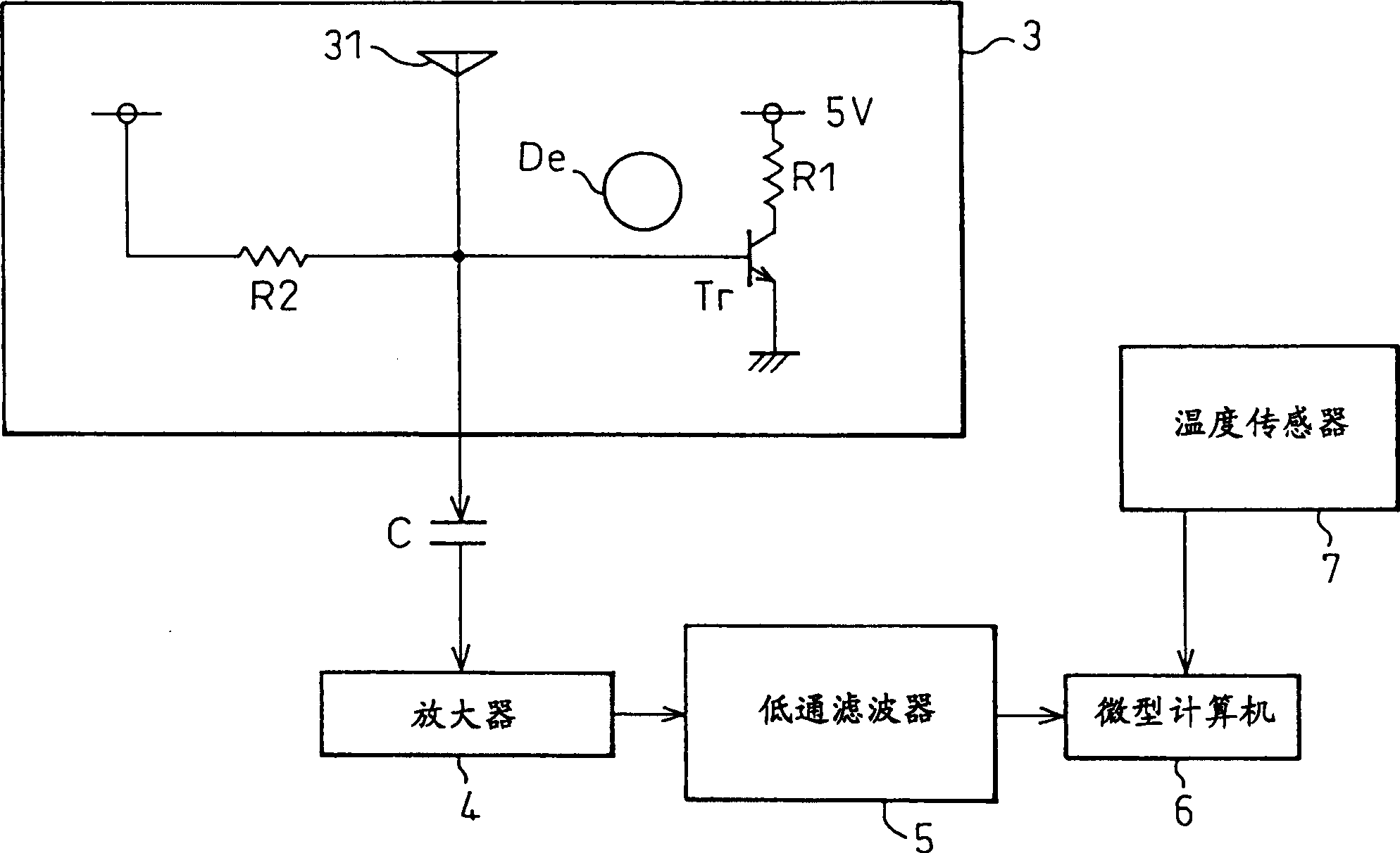
[0067] When there are people in the vehicle and it becomes a dangerous state, it mainly means that the temperature inside the vehicle rises to a high temperature or becomes a low temperature. Therefore, the effect is that instead of always monitoring whether there is a person in the vehicle, the sensor is activated to detect the presence of a human body in the vehicle when the temperature in the vehicle rises to a high temperature or is about to become high. Also, since this is not always detected, the possibility of detecting motion outside the vehicle can be reduced.
[0068] Figure 14 is a diagram illustrating the method of the present invention based on the above considerations. exist Figure 14 In , the horizontal axis is time, and the vertical axis is temperature in the vehicle. Always monitor the temperature inside the vehicle and activate the sensor when it becomes hot inside the vehicle. Such as Figure 14 As shown, when the temperature inside the vehicle reache...
Embodiment 3
[0071] In the case of the second embodiment, the sensor is activated after the dangerous temperature is reached to detect the presence or absence of a human body in the vehicle. However, in the case of the second embodiment, it takes several minutes after the sensor operates to detect the presence or absence of a human body in the vehicle, which may cause damage to the human body in the vehicle. In order to avoid this situation, in Embodiment 3, a device for monitoring the temperature gradient (inclination) in the vehicle is provided, and when the device predicts that the temperature rise (or drop) in the vehicle becomes a dangerous temperature, the sensor Work.
[0072] Figure 15 is a diagram illustrating the method of the present invention based on the above considerations. exist Figure 15 In , the horizontal axis is time, and the vertical axis is temperature in the vehicle. The temperature in the vehicle is constantly monitored, and when the temperature gradient in th...
PUM
 Abstract
Description
Claims
Application Information
 - R&D
- Intellectual Property
- Life Sciences
- Materials
- Tech Scout
- Unparalleled Data Quality
- Higher Quality Content
- 60% Fewer Hallucinations
Browse by: Latest US Patents, China's latest patents, Technical Efficacy Thesaurus, Application Domain, Technology Topic, Popular Technical Reports.
© 2025 PatSnap. All rights reserved.Legal|Privacy policy|Modern Slavery Act Transparency Statement|Sitemap|About US| Contact US: help@patsnap.com


