
Device for separating substance into two phases

A technology of materials and conveyors, applied in the field of devices where materials are separated into two phases, can solve problems such as inapplicability, and achieve the effect of increasing the flow surface

Inactive Publication Date: 2003-11-26
玛希斯·艾外瑞达思·安托尼斯
View PDF4 Cites 3 Cited by
  • Summary
  • Abstract
  • Description
  • Claims
  • Application Information

AI Technical Summary

Problems solved by technology

It needs special attention that the device is not suitable for dehydration of vegetables, plants, fertilizers, paper, wood and textile raw materials

Method used


Image

  • Device for separating substance into two phases
  • Device for separating substance into two phases

Examples


Embodiment Construction

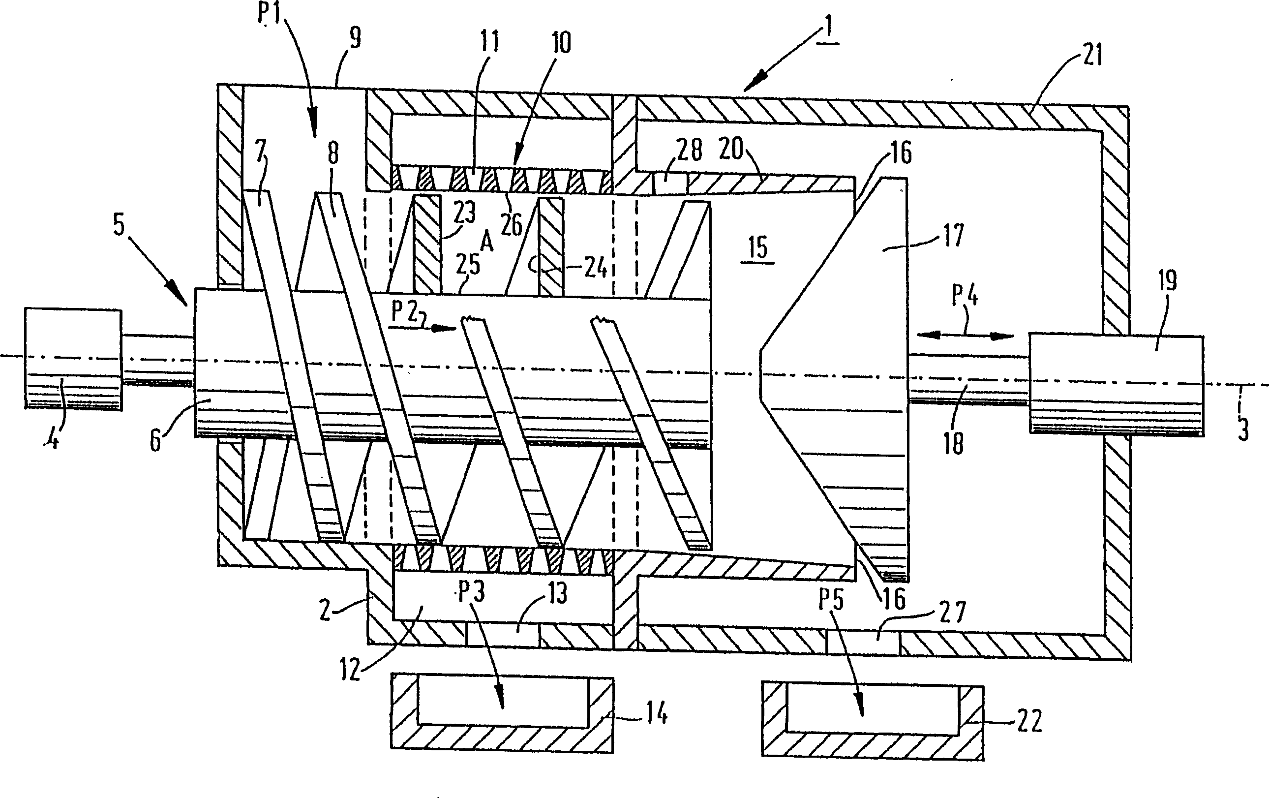
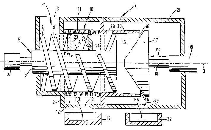
[0023] The separation device 1 according to the invention comprises a chamber 2 . The cavity 2 is shown as a whole in the figure, however in actual application the cavity 2 is composed of many interconnected parts. In the cavity 2 is provided a screw conveyor 5, which can be rotated around the axis 3 by the drive device 4. Aligned helices 7 and 8, the pitch of which increases in the conveying direction P2. On the cavity 2, there is an input port 9 for supplying materials to be separated by the screw conveyor 5 in the direction shown by the arrow P1. The rotation of the screws 7 and 8 will convey the material in the conveying direction P2. The central portion of the screw conveyor 5 in the length direction is surrounded by a cylindrical screen 10 . There are sieve holes in the circumferential direction of the cylindrical sieve 10 for passing the first phase in the material to be separated. In the present invention, the term screw length is used to represent the length of th...


PUM

PropertyMeasurementUnit
diameteraaaaaaaaaa

Abstract

The invention relates to a device (1) for separating a substance into two phases, which device (1) comprises a screw conveyor (5) including a shaft and at least one screw (5) which is mounted on said shaft, which screw conveyor extends between an intake opening (9) for the substance and an outlet opening (16) for one of said two phases, as well as a cylindrical screen (10) provided with screen openings (11), within the screw conveyor (5) is rotatably disposed for conveying the substance in a direction of transport from said intake opening (9) to said outlet opening (16) via flow surfaces lying in a radial plane between said shaft, two successive screw threads in said radial plane and the screen, and for discharging the other one of said two phases via said screen openings (11), wherein the screw length of the screw conveyor (5) is determined by the length of the screen within which the screw extends, and wherein the flow surface area increases along the entire screw lenth, seen in the direction of transport.

Description

technical field [0001] The invention relates to a device for separating materials into two phases, which device comprises a screw conveyor with a main shaft and at least one screw mounted on the main shaft and a cylindrical screen with sieve holes; the screw conveyor The device extends between the input port of the material and the output port of one of the two phases, and is rotatably arranged in the cylindrical screen for passing through the main shaft, two Flow surfaces in radial planes between the helical ribs and the screen convey material from the inlet to the outlet while the other of the two phases of said material is discharged through the screen openings, wherein the The length of the screw conveyor helix is ​​determined by the length of the screen in which the helix can extend. Within the framework of the present invention, the term "phase" is understood to mean in particular fractions with different densities. For greater clarity, the term flow surface is only us...

Claims


Application Information

Patent Timeline
Patent Type & Authority Applications(China)
IPC IPC(8): B01D29/94B30B9/12B01D29/25B30B9/14B30B9/18
CPCB30B9/18B30B9/12B30B9/121
Inventor 玛希斯·艾外瑞达思·安托尼斯
Owner 玛希斯·艾外瑞达思·安托尼斯
Learn More