Current-limiting armoured heating cable and element

An armored heating cable and heating element technology, applied in the direction of heating element material, heating element shape, etc., can solve the problems of limited use, poor life and reliability, large power consumption of aircraft, etc., to reduce power loss, improve working life and Reliability, fast heating and effect of automatic adjustment of heating power

Inactive Publication Date: 2003-11-12
CHONGQING MATERIALS RES INST
View PDF0 Cites 7 Cited by
  • Summary
  • Abstract
  • Description
  • Claims
  • Application Information

AI Technical Summary

Problems solved by technology

[0002] The traditional metal armored heater consists of alloy heating wire with constant resistivity, such as Ni80Cr20 alloy, etc., stainless steel metal sleeve and mineral insulating material magnesium oxide (MgO). Under the rated voltage, the heating power of the heating cable remains constant , the heating cable consumes a lot of power for the aircraft, and because it is in a constant high-power working state for a long time, its life and reliability are poor, and its use is limited

Method used


Image

  • Current-limiting armoured heating cable and element
  • Current-limiting armoured heating cable and element
  • Current-limiting armoured heating cable and element

Examples


Embodiment 1

[0010] Example 1: Heating Cable

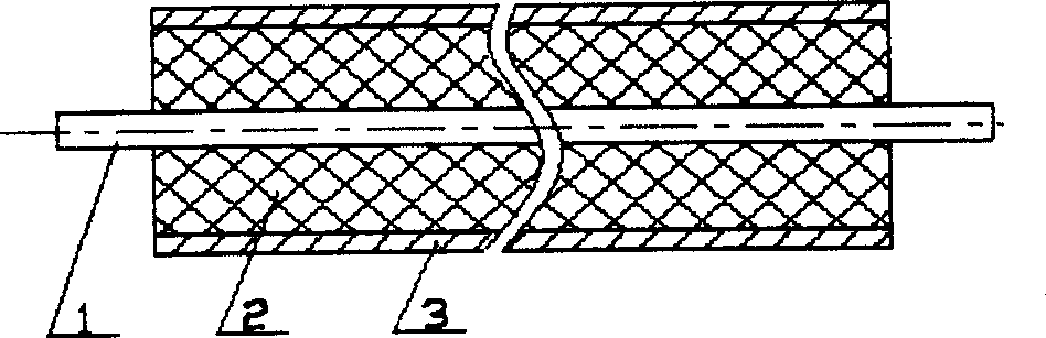
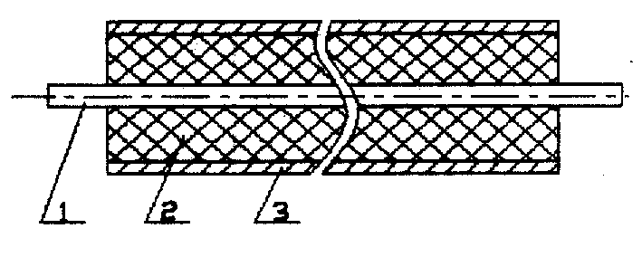
[0011] The chemical composition of the nickel-iron-based alloy heating wire is 70% Ni, 30% Fe. After vacuum smelting, thermal processing, cold processing and heat treatment, it is prepared into an alloy wire with a certain diameter, and it is combined with a metal sleeve (In.600, Stainless steel or pure nickel) and magnesium oxide insulating material are assembled into a metal armored cable blank, which is made into a current-limiting armored heating cable with a sleeve diameter of φ1.2mm after thermal processing, cold processing and heat treatment, and a core wire diameter of φ0.25mm , the room temperature unit resistance value is 3.3Ω / m, and its structure is as follows figure 1 , 1 is heating wire, 2 is magnesia insulating material, 3 is alloy casing, and its properties are shown in Table 1.

Embodiment 2

[0012] Example 2: Heating Cable

[0013] The composition, process and structure of the alloy heating core wire and heating cable are the same as in Example 1. The armored heating cable blank is processed by heat and cold deformation and heat treatment to prepare an armored heating cable with a diameter of φ1.0mm, and the diameter of the core wire is about φ0. 20mm, the room temperature unit resistance is 7.5Ω / m.

Embodiment 3

[0014] Example 3: Heating Element

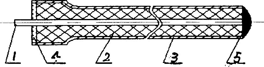
[0015] The composition of the alloy core wire and the heating cable is the same as in Example 1, and the formation of the element is to use one end of the armored heating cable as the working end, process the diameter reduction to φ0.7×1000mm, and weld the core wire and the sleeve at the working end connected to form a conductive circuit. The other end of the cable is the lead end, that is, the cold end. The lead wire and the sleeve of this end are sealed with insulating material, and the structure is as follows: figure 2 , 1 is heating wire, 2 is magnesia insulating material, 3 is alloy casing, 4 is working end solder joint, 5 is lead end. The room temperature resistance of the heating element is 9Ω, and the performance is shown in Table 2.


PUM

PropertyMeasurementUnit
Diameteraaaaaaaaaa
Diameteraaaaaaaaaa
Diameteraaaaaaaaaa

Abstract

The present invention relates to a current-limiting armored cable. It adopts the new type nickel-iron alloy heating thread, which chemistry element is that Ni:69-72%, Fe:31-28% w. The alloy thread and insulation material MgO powder are encapsulated in Inconel 600, the stainless steel or the nickel pipe to form the limiting current armored cable which diameter span is diameter 1.0-1.5 mm. Moreover the present invention provides a heating component made of the armored cable. The armored cable is machined into the changeable transect heating component, the end of the cable is welding point, and the other end is the sealed down-lead end. The ratio of the heating cable and the heating component is no little than 1.5. It can quickly heat and adjust heating power, increase the work life.

Description

technical field [0001] The invention relates to a metal casing armored heating cable and an element, which are used for anti-icing and de-icing heating of aircraft sensors. Different from traditional armored heating cables, this cable has the function of automatically adjusting the heating power as the temperature changes. Background technique [0002] The traditional metal armored heater consists of alloy heating wire with constant resistivity, such as Ni80Cr20 alloy, etc., stainless steel metal sleeve and mineral insulating material magnesium oxide (MgO). Under the rated voltage, the heating power of the heating cable remains constant , the heating cable consumes a lot of power for the aircraft, and because it is in a constant high-power working state for a long time, its life and reliability are poor, and its use is limited. Contents of the invention [0003] The purpose of the present invention is to overcome the shortcomings of traditional metal armored heaters, and ...

Claims


Application Information

Patent Timeline
IPC IPC(8): H05B3/12H05B3/40
Inventor 张平李多庄郭为民刘奇
Owner CHONGQING MATERIALS RES INST
Why Eureka
Try Eureka