Non-reversible circuit component

A technology of circuit components and strip conductors, which is applied in the direction of electrical components, circuits, waveguide devices, etc., can solve the problems of physical positional relationship and structural difficulties, and achieve the effect of small transmission loss

Inactive Publication Date: 2003-10-01
ALPS ALPINE CO LTD
View PDF0 Cites 2 Cited by
  • Summary
  • Abstract
  • Description
  • Claims
  • Application Information

AI Technical Summary

Problems solved by technology

Although in order to combine the multi-tuned circuit in the critical state, it is enough to make the center conductors slide in the up and down direction and separate from each other, but it is difficult to change the physical position relationship of the conductors in the up and down direction.

Method used


Image

  • Non-reversible circuit component
  • Non-reversible circuit component
  • Non-reversible circuit component

Examples


Embodiment Construction

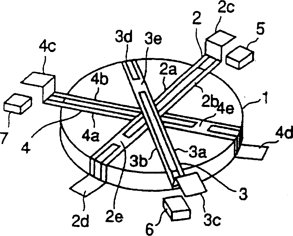
[0028] figure 1 The first embodiment of the present invention is shown. The magnetic core 1 made of disc-shaped ferrite such as yttrium iron garnet is placed in the DC magnetic field generated by the permanent magnet not shown in the figure, and its upper surface is at right angles to the direction of the DC magnetic field. Three central conductors 2, 3, 4 are placed on the magnetic core 1, and these central conductors 2 to 4 are kept insulated from each other, overlapped and maintained on the upper center of the magnetic core 1 at equiangular intervals (120°).

[0029] Each central conductor 2 to 4 is made up of 2 strip conductors facing each other at equal intervals and having the same width (respectively add a, b to represent such as 2a, 2b), and one end of each strip conductor is used as an input and output terminal (add respectively c is expressed as such as 2c), and the other end is used as a ground terminal (respectively adding d is expressed as such as 2d). In addit...


PUM


Abstract

The invention provides a non-reciprocal circuit element, which can ensure the transmission frequency band required by the input and output signals, reduce the loss on the signal frequency, and increase the return loss of the input and output terminals at the same time. The non-reciprocal circuit element of the present invention comprises: a plate-shaped magnetic core (1), placed in a DC magnetic field, the upper surface is at right angles to the direction of the DC magnetic field, and 3 central conductors (2, 3, 4) are overlapped at equal angular intervals placed on the roughly central part of the magnetic core (1), one end is used as the input and output terminals (2c, 3c, 4c), and the other end is used as the ground terminal (2d, 3d, 4d); make the center part to the ground terminal (2d , 3d, 4d) between the central conductor (2, 3, 4) unit length inductance ratio of the central part to the input and output terminals (2c, 3c, 4c) between the central conductor (2, 3, 4) unit The inductance of the length is small.

Description

technical field [0001] The invention relates to a non-reciprocal circuit element utilizing the Faraday effect. Background technique [0002] The main part of the previous nonreciprocal circuit element is shown in Figure 8 middle. The magnetic core 21 made of disc-shaped ferrite such as yttrium iron garnet is placed in the DC magnetic field generated by the permanent magnet not shown in the figure, and its upper surface is at right angles to the direction of the DC magnetic field. Three central conductors 22, 23, 24 are placed on the top of the magnetic core 21, they are kept insulated from each other, and are overlapped and maintained on the top center of the magnetic core 21 at equiangular intervals (120°). Also, their lengths are about equal to each other, so their inductance values ​​are also about the same. [0003] Each central conductor 22 to 24 is composed of two opposite strip conductors (respectively add a, b to indicate such as 22a, 22b), one end is used as an i...

Claims


Application Information

Patent Timeline
IPC IPC(8): H01P1/383H01P1/36H01P1/387
CPCH01P1/387
Inventor 清水祐一
Owner ALPS ALPINE CO LTD
Why Eureka
Try Eureka