
Flat permanent magnetic DC vibrating motor

A vibrating motor, permanent magnet DC technology, applied in the direction of electric components, electrical components, electromechanical devices, etc., can solve the problem of low utilization of winding space, achieve the effects of saving battery energy, facilitating mass production, and simplifying the structure

Inactive Publication Date: 2003-08-20
INST OF ELECTRICAL ENG CHINESE ACAD OF SCI
View PDF2 Cites 4 Cited by
  • Summary
  • Abstract
  • Description
  • Claims
  • Application Information

AI Technical Summary

Problems solved by technology

Its disadvantage is that only two of the three coil groups are energized to generate torque during operation, and the space utilization rate of the winding is low.

Method used


Image

  • Flat permanent magnetic DC vibrating motor
  • Flat permanent magnetic DC vibrating motor
  • Flat permanent magnetic DC vibrating motor

Examples


Embodiment Construction

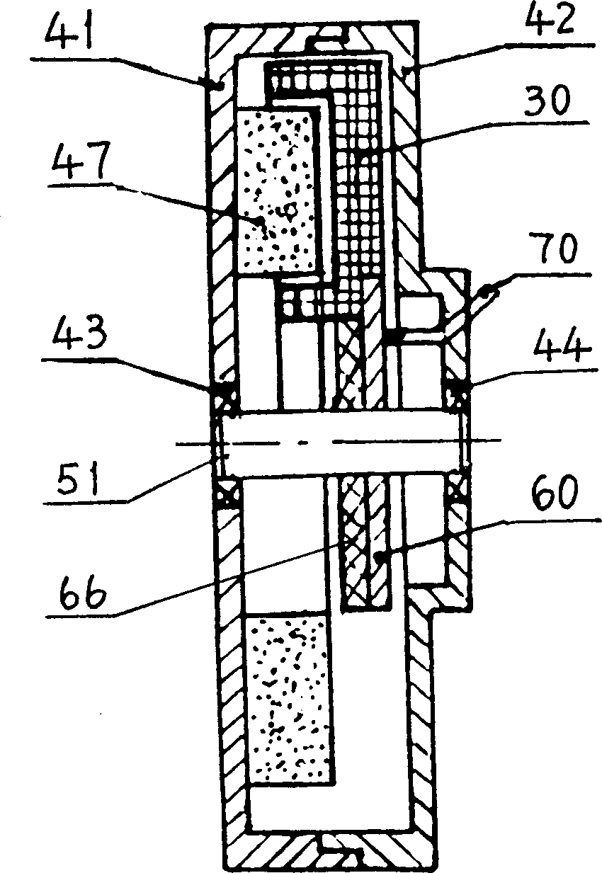
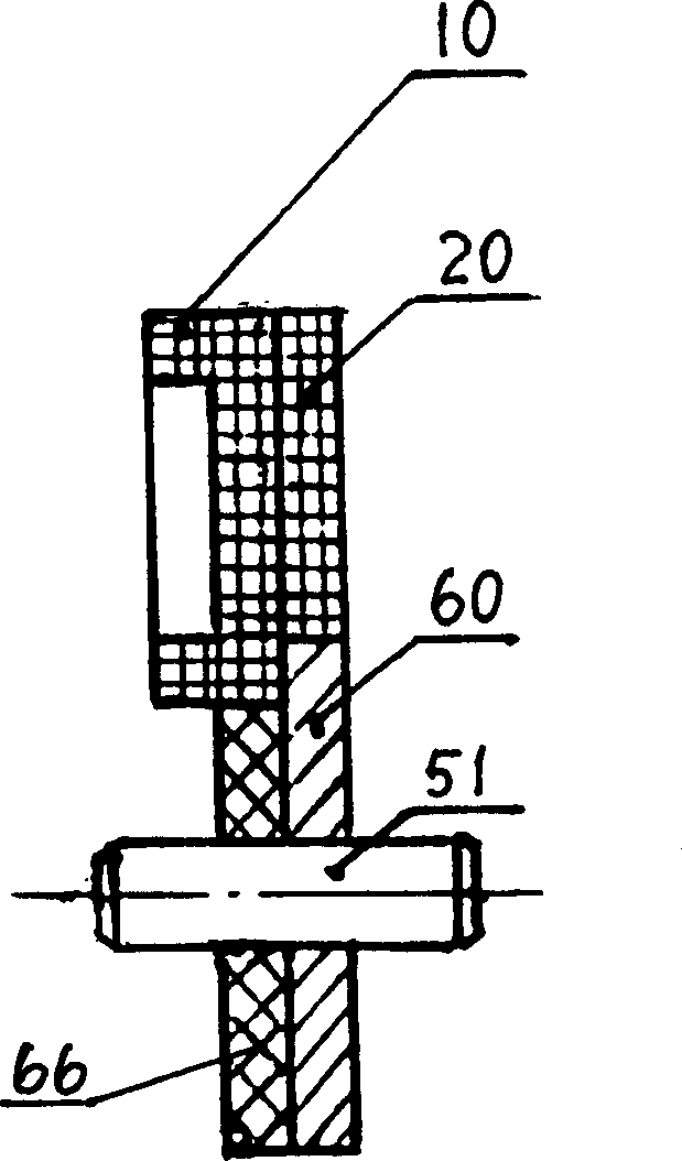
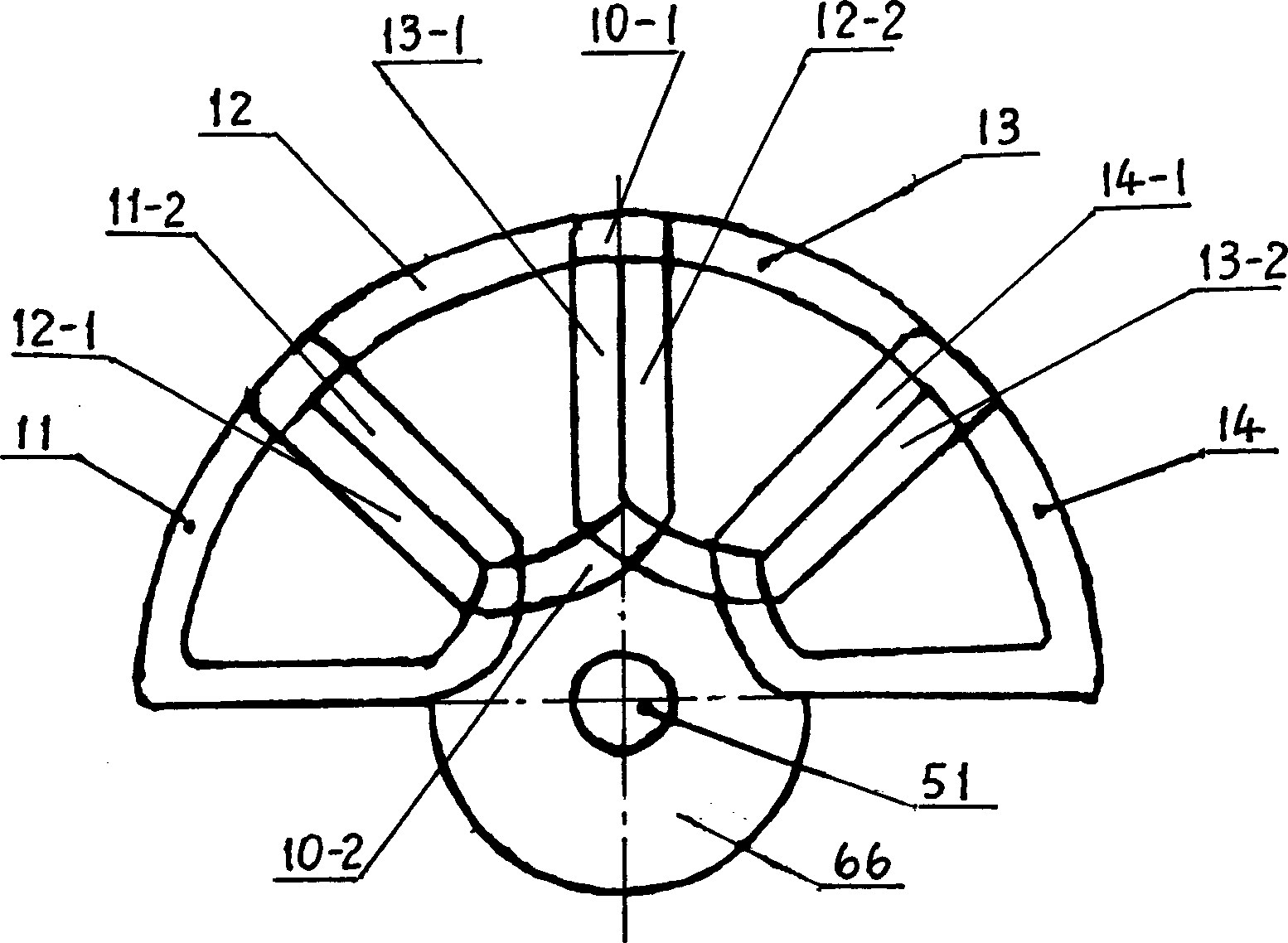
[0019] see first figure 1 . The flat permanent magnet DC vibration motor of the present invention includes a rotor 30 , a stator 40 , brushes and lead wires 70 . Wherein, the shell of the stator 40 is formed by fastening the left casing 41 and the right casing 42, figure 1 Shown in the left casing 41 left end inboard permanent magnet magnetic pole 47. In this embodiment, the number of pole pairs of the permanent magnetic poles 47 is 3, and the 6 magnetic poles are evenly distributed on the circular plane. One end of the permanent magnet pole 47 protrudes into the semicircular annular groove on the end surface of the rotor winding of the rotor 30 . The permanent magnet pole 47 is made of high-performance NdFeB permanent magnet material, and forms multiple pairs of poles through axial multi-pair magnetization. The left casing 41 and the right casing 42 of the stator are punched out with a high magnetic permeability thin plate. Two self-lubricating bearings 43 and 44 are riv...


PUM


Abstract

The flat permanent magnetic DC vibrating motor of the present invention is designed for soundless paging mechanism of mobile communicator. The rotor winding includes two parallel coils arranged in the axis direction and is end view fan-shaped in the same semi-circumference. The rotor winding has planar commutator built inside one of its ends. The permanent magnetic pole inside one end of the stator casing is stretched into semi-circular notch inside the end of the rotor winding with small axial air gap. The rotor winding, the planar commutator and the rotor shaft are assembled into one integral via plastic molding process and are installed on self-lubricating bearings inside the stator casing. The motor of the present invention has offset gravity center and needs no eccentric member matched.

Description

technical field [0001] The invention belongs to a motor, and relates to a flat permanent magnet direct current vibrating motor. The rotor winding has two groups of different coils arranged in the same semicircle to form an eccentric rotor, which is used in a silent calling mechanism of a mobile communication device. Background technique [0002] There is a vibration motor in the silent calling mechanism of the mobile communication device. For example, in the cylindrical coreless vibration motor with eccentric weight commonly used at present, the rotor has an eccentric component, and the axial dimension (thickness) of the motor is relatively large. [0003] Japanese Patent JP 2000166175 (Chinese Patent Publication No. CN 1255762) discloses a flat vibrating motor, the rotor adopts a single-layer winding structure, the stator magnetic poles are two pairs of poles, and the three concentrated coil groups of the rotor winding are evenly distributed in a semicircle . Its disadvan...

Claims


Application Information

Patent Timeline
Patent Type & Authority Applications(China)
IPC IPC(8): H02K3/28H02K7/065H02K7/075
Inventor 李世毅
Owner INST OF ELECTRICAL ENG CHINESE ACAD OF SCI
Learn More