Baseplate for arm and suspension assembly

A suspension, substrate technology, applied in the installation of arm parts, alignment of tracks on magnetic disks, configuration/installation of recording heads, etc. Some stout and other problems

Inactive Publication Date: 2003-06-11
SAE MAGNETICS (HK) LTD
View PDF2 Cites 3 Cited by
  • Summary
  • Abstract
  • Description
  • Claims
  • Application Information

AI Technical Summary

Problems solved by technology

Consequently, the load beam welded to the edge of the substrate is deformed due to deflection of the edge of the substrate, detrimentally affecting the gram load on the sensing head and the holdin

Method used


Image

  • Baseplate for arm and suspension assembly
  • Baseplate for arm and suspension assembly
  • Baseplate for arm and suspension assembly

Examples


Embodiment Construction

[0030] In the figures, the same reference numbers refer to the same elements. It should be understood that the dimensions of the various features in the drawings may not be to scale, or may not be to exact scale, but are shown for clarity and explanatory purposes.

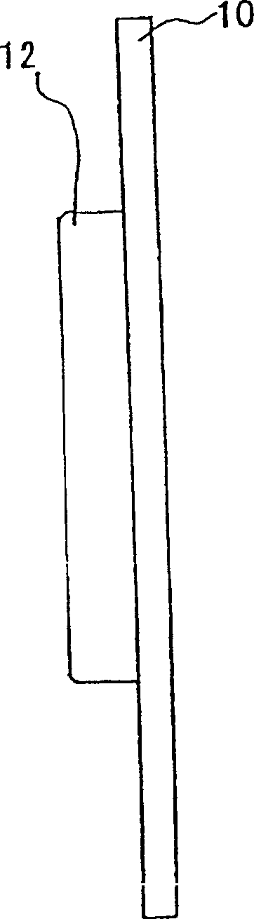
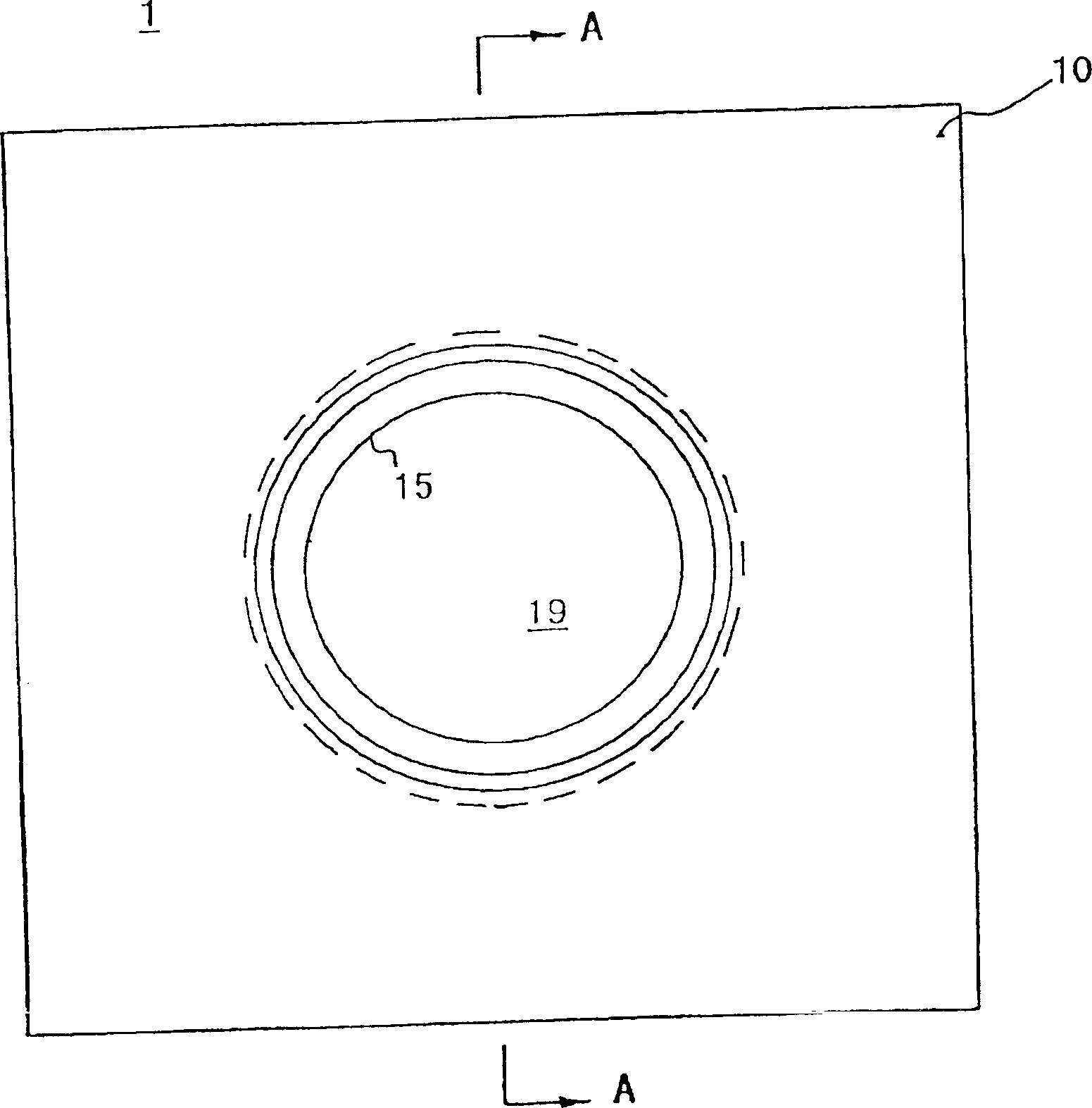
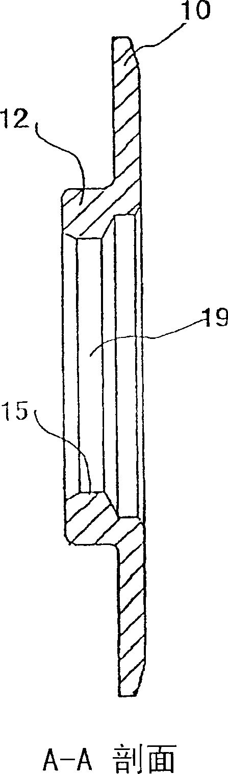
[0031] See Figure 1 and figure 2 . An actuator arm, which is an element of a head stack assembly (HSA), and a sensor suspension assembly are connected end-to-end through a substrate, which is part of the sensor suspension assembly. The base plate, generally designated 1 , includes a flat edge portion 10 and a cylindrical hub portion or boss 12 . The base plate is generally in the shape of an inner cylinder with a counterbore 11 , a fillet chamfer 13 and an inner diameter portion 15 . The counterbore 11 and inner diameter portion 15 are perpendicular to the plane of the substrate edge 10 . The hub 12 is inserted into the load beam boss clearance hole of the load beam 14, and the edge portion 10 is welded to the...


PUM


Abstract

The present invention provides a baseplate comprising a cylindrical hub, a flat flange, and one or two circular notches of a "V" or "U" shape etc. formed in said flange. This baseplate has the advantages of smaller deformation and larger retention torque during swage operation. Also it is easy to make and has no further cost in production. Moreover, the present invention further provides an arm and suspension assembly equipped with the baseplate and a hard disk drive equipped with the arm and suspension assembly.

Description

technical field [0001] The present invention relates to a disk head assembly for supporting a read / write head adjacent to a spinning disk in a disk drive, and more particularly, the invention relates to a base plate for mounting a head suspension assembly to a head actuator arm . Background technique [0002] In a hard disk drive, multiple spinning platters are mounted in a coaxial stack inside the drive housing, and data is stored on the magnetizable surfaces of the platters. A drive mechanism supports the transducing head for writing data to and reading data from the disk surface, the drive mechanism is mounted on the housing and is actuatable to position the transducing head in alignment with concentric data tracks defined on the disk. Each transducing head is fixed at one end of a head suspension connected to a drive arm protruding from the drive body. The suspension consists of a bent and formed flexible load beam of thin steel sheet. The load beam acts as a spring f...

Claims


Application Information

Patent Timeline
IPC IPC(8): G11B5/48G11B5/54G11B5/596G11B21/16
CPCG11B5/4813
Inventor 王烈志吴凯
Owner SAE MAGNETICS (HK) LTD
Why Eureka
Try Eureka